volkswagen Workshop Repair Guides

Volkswagen Workshop Service and Repair Manuals

Connecting vehicle diagnosis, testing and information system VAS 5051 and selecting engine control unit > < Significance of EPC warning lamp (fault lamp for electronic accelerator) in dash panel insert
Motronic inj. and ignition system (2-valve, roller rocker finger)
General to self-diagnosis
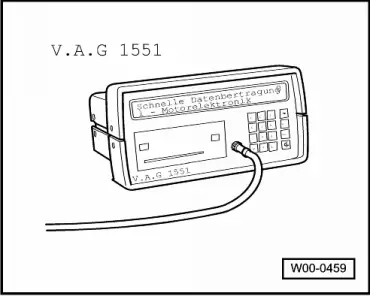
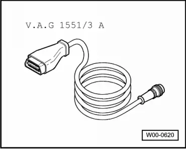
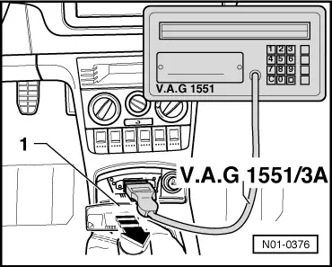
Connecting fault reader V.A.G 1551 and selecting engine electronics control unit
 
W00-0459

Special tools, workshop equipment, testers, measuring instruments and auxiliary items required

  • ◆ → V.A.G 1551 Fault reader

Note:

The vehicle system tester V.A.G 1552 can be used instead of the fault reader V.A.G 1551, however a print-out is not possible.

All functions of V.A.G 1551/1552 can also be carried out with the new tester V.A.S 5051. Connecting VAS 5051 .

 
W00-0620
  • ◆ → V.A.G 1551/3A Cable

Test conditions

 
N24-0831
  • ● → The fuses No. 1, 3, 15, 24, 30, 31, 34, 36 and 40 must be OK.
  • ● Earth connection between engine (on gearbox bell housing) and body (below battery) OK.
  • ● Earth connection in plenum chamber OK.
  • ● The battery voltage must be at least 11.5 V.
  • ● If the vehicle is equipped with an air conditioning system, this must be switched off.
  • ● All electrical consumers, e.g. lights and rear window heating must be switched off.
 
N01-0376

Work sequence

  • ‒ → Pull cover -1- off in direction of arrow.
  • ‒ Connect fault reader V.A.G 1551 or vehicle system tester V.A.G 1552 with cable V.A.G 1551/3A.

After the fault reader has been connected:

  • ‒ Depending upon desired function:
    Switch ignition on
         or
    Start engine , Table "Selectable functions".

Notes:

  • ◆ If the display remains blank, check voltage supply for diagnostic connection according to fault finding programme:

=> Current flow diagrams, Electrical fault finding and Fitting locations

  • ◆ If the display does not indicate as described in the work sequence:

=> Fault reader operating instructions

  • ◆ If due to an input fault "Fault in the data transfer!" is displayed, pull wire off fault reader, reconnect and repeat work step.
  • ‒ Operate fault reader taking into account the information on the display:
 
→ Indicated on display:
V.A.G - SELF DIAGNOSIS     HELP
     1 - Rapid data transfer*
     2 - Flash code output*

* Appears alternately

  • ‒ Operate fault reader taking into account the information on the display:
  • ‒ Press key 1 for "Rapid data transfer".
  • ‒ Press keys 0 and 1 for address word "Engine electronics" and confirm entry with Q key.
 
→ The control unit identification and the coding will appear on the display, e.g.:
030906032G
  • ◆ 030906032G = Part No. of control unit (for up-to-date control unit version see parts film)
  • ◆ ME 7.5.10 = System designation and version
  • ◆ 2921 = Program level number
  • ◆ Coding XXXXX = Control unit coding
  • ◆ WSC xxxxx = Workshop code from V.A.G 1551, of the workshop who carried out the last coding. (If the factory coding has not been changed, WSC 00000 appears)

Note:

Replace control unit if the control version displayed does not correspond to the vehicle

=> Page 24-135 .

An incorrectly coded engine control unit leads to:

  • ◆ Engine running faults (gear change jerks, load change jerks, etc.)
  • ◆ Increased fuel consumption
  • ◆ Increased exhaust gas emissions
  • ◆ Faults stored in fault memory which are not actually present
  • ◆ Functions will not be performed (Lambda regulation, activation of the activated charcoal filter system, etc.).
  • ‒ Press ⇒key.
 
→ Indicated on display:
Rapid data transfer     HELP
Select function XXX
  • ‒ Further measures see repair procedures.

Connecting vehicle diagnosis, testing and information system VAS 5051 and selecting engine control unit > < Significance of EPC warning lamp (fault lamp for electronic accelerator) in dash panel insert