volkswagen Workshop Repair Guides

Volkswagen Workshop Service and Repair Manuals

Fault memory > < Connecting fault reader V.A.G 1551 and selecting engine electronics control unit
Motronic inj. and ignition system (2-valve, roller rocker finger)
General to self-diagnosis
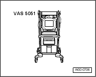
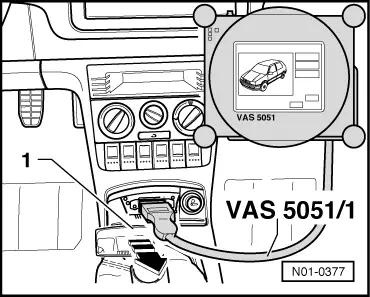
Connecting vehicle diagnosis, testing and information system VAS 5051 and selecting engine control unit
 
W00-0706

All the functions that were previously possible with the V.A.G 1551/1552 can be performed with the new tester VAS 5051 in operating mode Vehicle self-diagnosis:

=> Operating instructions for Vehicle Diagnosis, Testing and Information System VAS 5051.

Special tools, workshop equipment, testers, measuring instruments and auxiliary items required

  • ◆ → VAS 5051 Vehicle Diagnosis, Testing and Information System

Test conditions

 
N24-0831
  • ● → The fuses No. 1, 3, 15, 24, 30, 31, 34, 36 and 40 must be OK.
  • ● Earth connection between engine (on gearbox bell housing) and body (below battery) OK.
  • ● Earth connection in plenum chamber OK.
  • ● The battery voltage must be at least 11.5 V.
  • ● If the vehicle is equipped with an air conditioning system, this must be switched off.
  • ● All electrical consumers, e.g. lights and rear window heating must be switched off.

Work sequence

 
N01-0377
  • ‒ → Pull cover -1- off in direction of arrow.
  • ‒ Connect tester VAS 5051 with diagnosis cable VAS 5051/1 or VAS 5051/3 as follows:
  • ‒ Fit diagnosis cable connector onto diagnosis connector.
  • ‒ Depending upon desired function:
    Switch ignition on
         or
    Start engine , Table "Selectable functions".

Note:

  • ◆ The display fields will be displayed from top to bottom in functions 04 - Basic settings or 08 - Read data block.
  • ◆ If the display does not indicate as described in the work sequence:

=> Operating instructions for Vehicle Diagnosis, Testing and Information System VAS 5051.

 
N01-0228

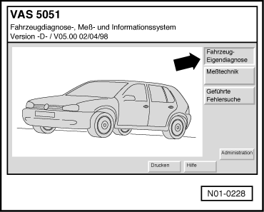
→ Indicated on display:

Selecting operating mode:

  • ‒ Press the button on the display for "Vehicle self-diagnosis" -arrow-.
 
N01-0229

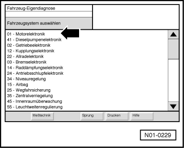
→ Indicated on display:

Selecting vehicle system:

  • ‒ Press "01 - Engine electronics" on display -arrow-.
 
N01-0230

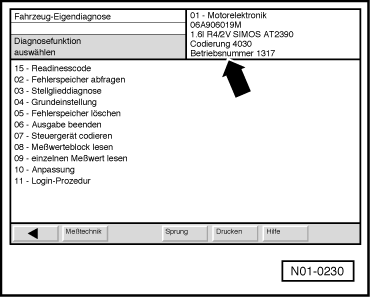
→ The control unit identification and coding -arrow- is shown on display e.g.:

Note:

Replace control unit if the control version displayed does not correspond to the vehicle

=> Page 24-135 .

 
N01-0231

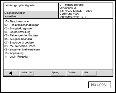
→ Indicated on display:

Selecting diagnosis function:

At this point all diagnosis functions are available.

  • ‒ Press desired function on display.
  • ‒ Further measures see repair procedures.

Fault memory > < Connecting fault reader V.A.G 1551 and selecting engine electronics control unit