volkswagen Workshop Repair Guides

Volkswagen Workshop Service and Repair Manuals

Checking fuel pressure regulator and holding pressure > < Checking air conditioner and air conditioner compressor signals
Motronic injection and ignition system
Servicing injection system
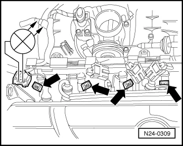
Checking injectors

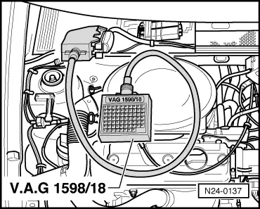
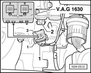
Checking activation

Special tools, testers, measuring instruments and auxiliary items required

  • ◆ Test box V.A.G 1598/18
  • ◆ Hand multimeter V.A.G 1526 or multimeter V.A.G 1715
  • ◆ Diode test lamp V.A.G 1527
  • ◆ Adapter set V.A.G 1594
  • ◆ Current flow diagram

Check conditions

  • ● Hall sender in distributor must be OK.
  • ● Fuel pump relay must be OK

Test sequence

  • ‒ Remove air cleaner , Fig. 2 .
 
N24-0309
  • ‒ → Pull connector off injectors -arrows-.
  • ‒ Connect diode test lamp V.A.G 1527 using aux. cables from V.A.G 1594 to connector contacts of Cyl. 1.
  • ‒ Operate starter.
         The LED must flicker
  • ‒ Repeat check at the injector connectors Cyl. 2...4.

The LED does not flicker on any cylinder:

 
N24-0310
  • ‒ → Connect diode test lamp to connector Cyl. 1, contact 1 and earth.
  • ‒ Operate starter.
         The LED must light up

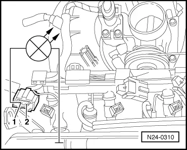
If the LED does not light up:

  • ‒ Check wire between 2 pin connector contact 1 and fuel pump relay (J17) for open circuit according to current flow diagram.
         Wire resistance: max. 1.5 ω

The LED flickers on one or several cylinders:

 
N24-0137
  • ‒ → Connect test box V.A.G 1598/18 to control unit wiring loom.
  • ‒ Check wiring between test box and connectors of injectors for open circuit according to current flow diagram.
         Cyl. 1 connector, contact 2+socket 7
         Cyl. 2 connector, contact 2+socket 6
         Cyl. 3 connector, contact 2+socket 28
         Cyl. 4 connector, contact 2+socket 4
         Wire resistance: Max. 1.5 ω
  • ‒ Additionally check wires for short to one another.
         Specification: ∞ω
  • ‒ Check wiring between connector contacts 1 of injectors for open circuit.
         Wire resistance: Max. 1.5 ω
 
N24-0311
  • ‒ Additionally check wires for short to one another.
         Specification: ∞ω

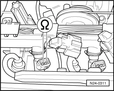
Checking resistance of injectors with wiring

  • ‒ → Check of resistance injectors between contacts.
         Specification: 14...17 ω

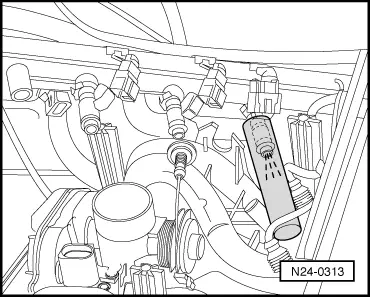
Checking spray pattern and for leaks

Special tools, testers, measuring instruments and auxiliary items required

  • ◆ Adapter set V.A.G 1594
  • ◆ Digital potentiometer V.A.G 1630
  • ◆ Measuring unit V.A.G 1602

Test sequence

  • ‒ Pull 3 pin connector off ignition transformer.
 
N24-0312
  • ‒ → Pull 4 pin connector -1- off coolant temperature sender (G62) -2-.
  • ‒ Connect digital potentiometer V.A.G 1630 using aux. cables from V.A.G 1594 to connector contacts 1+3 and set connected side to 15 kω.
  • ‒ Pull connector off throttle valve control part, oil pressure switch and intake manifold pressure sender, and unclip wiring at intake pipe and coolant regulator housing.
  • ‒ Remove fuel manifold complete with all injectors from intake pipe (fuel hoses remain connected).
 
N24-0313
  • ‒ → Hold a small container under the injector to be checked and pull connectors off all other injectors.
  • ‒ Operate starter, using a 2nd person. Injector must spray pulsatingly.
  • ‒ Repeat check with other injectors ensuring that injector to be checked is only connected.
  • ‒ Switch off ignition and afterwards check injectors for leaks. No more than
         2 drops/min
    may leak from each injector.

Note:

When installing the injectors ensure that the O rings

are not damaged.

Checking fuel pressure regulator and holding pressure > < Checking air conditioner and air conditioner compressor signals