volkswagen Workshop Repair Guides

Volkswagen Workshop Service and Repair Manuals

Checking signal from clutch pedal switch > < Checking engine speed signal
Simos injection and ignition system
Checking additional signals
Checking signal from/to air conditioning system

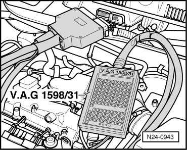
Function

Air conditioner compressor signal:
Just before the air conditioner compressor is switched on, the voltage is sent to the engine control unit. The signal ensures that once the air conditioner is switched on, idling speed will not drop drastically.

Switching off air conditioner compressor:
In order that engine performance is not impaired when accelerating, the A/C compressor is switched off briefly when accelerating from start or from low engine revs.

Air conditioner readiness:
When the air conditioner is switched on the engine control unit receives the information: air conditioning system is switched on. This "PWM signal" (pulse width modulation) can be used to pre-control the idling speed.

Special tools, workshop equipment, testers, measuring instruments and auxiliary items required

  • ◆ Hand multimeter V.A.G 1526 or multimeter V.A.G 1715
  • ◆ Fault reader V.A.G 1551 (or vehicle system tester V.A.G 1552) with cable V.A.G 1551/3
  • ◆ Adapter set V.A.G 1594
  • ◆ Test box V.A.G 1598/31
  • ◆ Current flow diagram

Test conditions

  • ● All electrical consumers, e.g. lights and rear window heating must be switched off.
  • ● Air conditioner functioning OK.
  • ● Air conditioner must be switched off
  • ● Vehicle at room temperature (warmer than + 15 °C).
  • ● No faults must be stored in fault memory , interrogating and erasing fault memory.

Test sequence

  • ‒ Connect fault reader V.A.G 1551 (V.A.G 1552). Start engine and select "Address word" 01 of engine control unit. When doing this the engine must be running at idling speed.
    (Connecting fault reader and selecting engine control unit => Page 01-10 .)
 
→ Indicated on display:
Rapid data transfer     HELP
Select function XXX
  • ‒ Press keys 0 and 8 for the function "Read measured value block" and confirm entry with Q key.
 
→ Indicated on display:
Read measured value block
Input display group number XXX

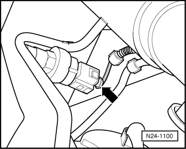
Checking air conditioner compressor signal and air conditioner switch-off

  • ‒ Press keys 0, 5 and 0 for "Display group number 50" and confirm entry with Q key.
 
→ Indicated on display:
(1...4 = Display zones)
Read measured value block 50     ⇒
     1     2     3     4
  • ‒ Check displays in display zones 3 and 4:
  • Display in display zone 3:
         Off
  • Display in display zone 4:
         Compr.OFF
  • ‒ Switch on air conditioning system.
  • ‒ Select lowest temperature and highest blower speed.
  • The display in display zone 3 must change to
         on.
  • Display in display zone 4 must change to
         Compr.ON.
  • ‒ Carry out test drive with a 2nd person to observe display.

Observe the valid safety precautions when carrying out a road test => Page 24-28 .

Note:

A road test is required to test the shut-off function.

  • ‒ Engage 1st gear and accelerate moderately hard. Then release accelerator pedal.
  • The display in display zone 4 must change from
         Compr.ON
    to
         Compr. OFF
    for a few seconds (compressor switch-off when vehicle is accelerating), during which the display in display zone 3 must remain constantly at "on".
  • ‒ Press the ⇒key.
  • ‒ Switch off air conditioning system.

If the display changes as described:

  • ‒ Checking air conditioner readiness => Page 24-146 .

If the displays do not change as described:

  • ‒ Press keys 0 and 6 for the "End output" function and confirm input with the Q key.
 
N24-0943
  • ‒ Switch off ignition.
  • ‒ → Connect test box V.A.G 1598/31 to control unit wiring harness. The engine control unit remains disconnected.
  • ‒ Check wiring between test box sockets 76 and the air conditioner for open circuit using current flow diagram.
         Wire resistance: Max. 1.5 ω
  • ‒ Check the wire between text box socket 28 and the air conditioner for open circuit using current flow diagram.
         Wire resistance: Max. 1.5 ω

Checking air conditioner readiness

Note:

The engine control unit receives a "PWM signal" from air conditioning system high pressure sender (G65), this allows the idling speed signal to be regulated more precisely.

  • ‒ Press keys 0 and 8 for the function "Read measured value block" and confirm entry with Q key.
 
→ Indicated on display:
Read measured value block
Input display group number XXX
  • ‒ Press keys 0, 5 and 7 for "Display group number 57" and confirm entry with Q key.
 
→ Indicated on display:
(1...4 = Display zones)
Read measured value block 57     ⇒
     1     2     3     4
  • ‒ Observe display in display zone 4. It must show
         0...2 %
  • ‒ Switch on air conditioning system.
  • ‒ Select lowest temperature and highest blower speed.
  • The display in display zone must change to
         15...80% (fluctuating).
  • ‒ Press the ⇒key.
  • ‒ Press keys 0 and 6 for the "End output" function and confirm input with the Q key.
  • ‒ Switch off ignition.

If the display does not change or remains constantly at 0%:

  • ‒ Remove noise insulation tray.
 
N24-1100
  • ‒ → Pull 3-pin connector off air conditioning system high pressure switch (G65) -arrow-.
 
N24-1101
  • ‒ → Connect multimeter to measure voltage using aux. cables from V.A.G 1594 to contacts 2 (positive) and 3 (earth) on high pressure sender connector.
  • ‒ Switch on ignition.
         Specification: min. 11.5 V
  • ‒ Switch off ignition.

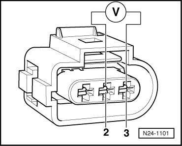
If no voltage is present:

 
N24-0943
  • ‒ → Connect test box V.A.G 1598/31 to control unit wiring harness. The engine control unit remains disconnected.
 
A24-0096
  • ‒ → Check wiring for open circuit between test box and 3-pin connector referring to current flow diagram:
         Contact 2 and test box socket 29
         Wire resistance: max. 1.5 ω
  • ‒ Check wiring additionally for short to vehicle earth or battery positive.
         Specification: ∞ω

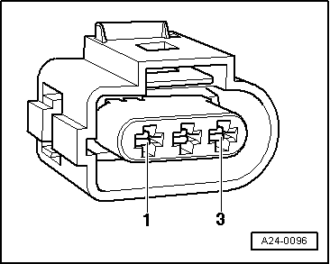
If no wiring fault is detected:

  • ‒ Renew high pressure sender (G65)

=> Heating, Air conditioning; Repair group 87

Checking signal from clutch pedal switch > < Checking engine speed signal