volkswagen Workshop Repair Guides

Volkswagen Workshop Service and Repair Manuals

Checking fuel pressure regulator and holding pressure > < Checking engine speed sender
Simos injection and ignition system
Checking components
Checking injectors

Special tools, workshop equipment, testers, measuring instruments and auxiliary items required

  • ◆ Hand multimeter V.A.G 1526 or multimeter V.A.G 1715
  • ◆ Diode test lamp V.A.G 1527
  • ◆ Adapter set V.A.G 1594
  • ◆ Test box V.A.G 1598/31
  • ◆ Current flow diagram

Check conditions

 
N24-0831
  • ● → Fuse No. 3 must be OK.
  • ● The battery voltage must be at least 11.5 V.
  • ● Earth connection in plenum chamber OK.
  • ● All electrical consumers, e.g. lights and rear window heating must be switched off.
  • ● If the vehicle is equipped with an air conditioning system, this must be switched off.
  • ● Fuel pump relay must be OK , final control diagnosis.
  • ● Engine speed sender must be OK, checking .
 
N28-0102
  • ● Hall sender must be OK, checking
    .

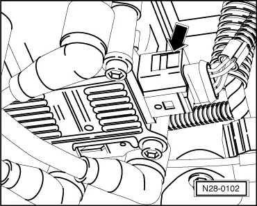
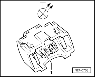
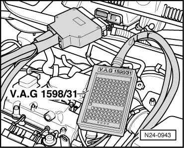
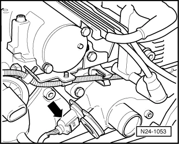
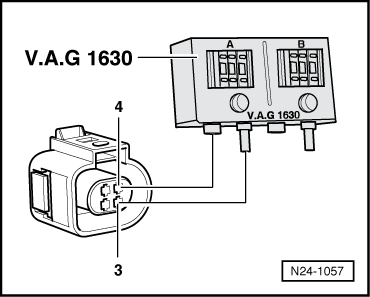
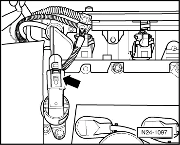
Checking activation and voltage supply

  • ‒ Remove cover over camshaft housing , Fig.1 .
  • ‒ → Pull 4 pin connector off ignition transformer (N152) -arrow-.
 
N24-0736
  • ‒ → Pull plug -arrows- off all injectors.
 
N24-0767
  • ‒ → Connect diode test lamp V.A.G 1527 using aux. cables from V.A.G 1594 to connector contacts of Cyl. 1.
  • ‒ Operate the starter and check the voltage supply for No. 1 cylinder injector.
         The LED must flicker
  • ‒ Repeat check at the injector connectors for Cyls. 2...4.
  • ‒ Switch off ignition.

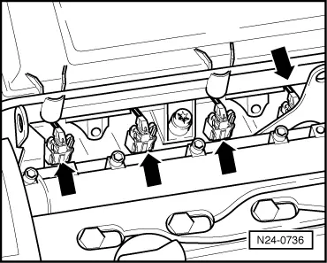
If the LED flickers on one or several cylinders:

 
N24-0768
  • ‒ → Connect diode test lamp to contact 1 and earth of relevant injector connector.
  • ‒ Operate the starter and check the voltage supply for No. 1 cylinder injector.
         The LED must light up
  • ‒ Repeat check at the injector connectors for Cyls. 2...4.
  • ‒ Switch off ignition.

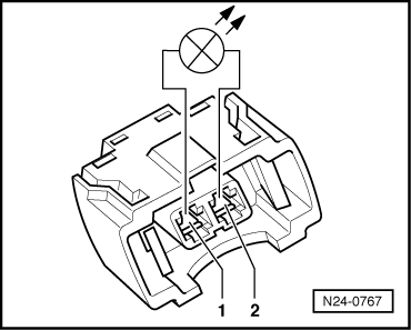
If the LED does not light up:

  • ‒ Check wire between 2 pin connector contact 1 and fuel pump relay (J17) for open circuit using current flow diagram.
         Wire resistance: max. 1.5 ω
 
N24-0943

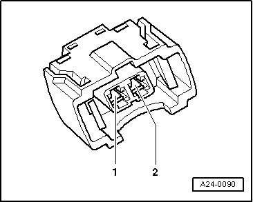
If the LED does not light up on one or several cylinders:

  • ‒ → Connect test box V.A.G 1598/31 to control unit wiring harness. The engine control unit remains disconnected.
 
A24-0090
  • ‒ → Check wiring for open circuit between test box and 2-pin connector referring to current flow diagram.
         Injector 1: Contact 2 and socket 88
         Injector 2: Contact 2 and socket 87
         Injector 3: Contact 2 and socket 85
         Injector 4: Contact 2 and socket 86
         Wire resistance: max. 1.5 ω
  • ‒ Additionally check wires for short to one another between contacts 2 to vehicle earth and to battery positive.
         Specification: ∞ω
  • ‒ Check wiring between connector contacts 1 of injectors for open circuit to one another.
         Wire resistance: Max. 1.5 ω

If no fault is detected in the wiring:

  • ‒ Check resistance of injectors
    .

Checking resistance of injectors

 
A96-0134
  • ‒ → Check resistance of injectors between contacts.
         Specification: 12.0...17.0 ω(at room temperature)

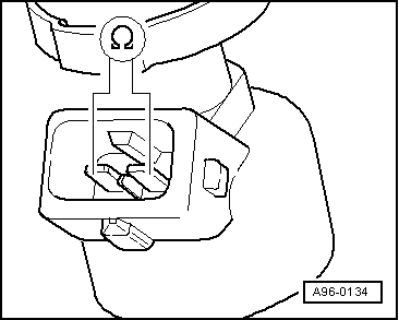
Note:

The resistance figures are valid for approx. 20 °C. At higher temperatures the resistance figures will increase.

If the specification is not attained:

  • ‒ Remove air cleaner => Page 24-26 , Fig. 2 .
  • ‒ Renew defective injector
    , item 7 .

Perform installation of injectors in reverse order. When doing this note the following:

  • ◆ Renew O-rings on all injectors and lightly moisten with clean engine oil.
  • ◆ Insert injectors vertically and in the correct position into the fuel rail and secure with retaining clips.
  • ◆ With injectors secured to fuel rail, fit fuel rail on intake manifold and press in evenly.
  • ‒ Interrogate fault memory, if necessary, repair any faults and then erase fault memory => Page 01-20 , interrogating and erasing fault memory.
  • ‒ Erase the learnt values and adapt the engine control unit again=> Page 24-128 .

If the resistances are OK and no faults can be detected in the wiring:

  • ‒ Replace engine control unit
    => Page 24-121 .
 
W24-0003

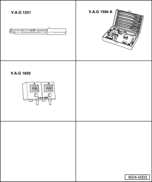
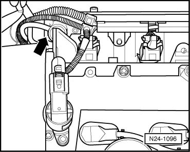
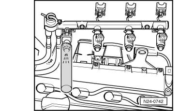
Checking spray pattern and for leaks

Special tools, workshop equipment, test and measuring appliances and auxiliary items required

  • ◆ V.A.G 1331 Torque wrench (5...50 Nm)
  • ◆ V.A.G 1594 A Adapter set
  • ◆ V.A.G 1630 Digital potentiometer
  • ◆ Measuring container

Test conditions

  • ● The fuel pressure must be in order, checking
    => Page 24-83 , checking fuel pressure regulator and holding pressure.
 
N28-0102

Test sequence

  • ‒ Remove air cleaner => Page 24-26 , Fig. 2 .
  • ‒ → Pull 4 pin connector off ignition transformer (N152) -arrow-.
 
N24-1053
  • ‒ → Pull the 4 pin connector off coolant temperature sender (G62) with coolant temperature gauge sender (G2) -arrow-.
 
N24-1057
  • ‒ → Connect digital potentiometer V.A.G 1630 using aux. cables from V.A.G 1594 to connector contacts 3+4 and set connected side to 15 kω.
 
N24-1096
  • ‒ → Pull the vacuum hose off fuel pressure regulator -arrow-.
 
N24-1097
  • ‒ → Disconnect 2-pin connector from camshaft adjustment valve(N205) -arrow-.
 
N24-0736
  • ‒ → Pull plug -arrows- off all injectors.
  • ‒ Unclip injector wiring harness on fuel rail.
  • ‒ Remove fuel rail complete with all injectors from intake manifold (fuel hoses remain connected)
    => Page 24-12 , item 9 .
 
N24-0742
  • ‒ → Hold a small container under the injector to be tested and fit the connector.
  • ‒ Have 2nd person operate starter. Injector must spray in pulses.
  • ‒ Repeat check with other injectors ensuring that injector to be checked is only connected.
  • ‒ Switch off ignition.
  • ‒ Switch off ignition and afterwards check injectors for leaks. No more than
         2 drops/min
    may leak from each injector.

If the fuel loss is greater:

  • ‒ Renew defective injector
    , item 7 .

Perform installation of injectors in reverse order. When doing this note the following:

  • ◆ Renew O-rings on all injectors and lightly moisten with clean engine oil.
  • ◆ Insert injectors vertically and in the correct position into the fuel rail and secure with retaining clips.
  • ◆ With injectors secured to fuel rail, fit fuel rail on intake manifold and press in evenly.
  • ‒ Interrogate fault memory, if necessary, repair any faults and then erase fault memory => Page 01-20 , interrogating and erasing fault memory.
  • ‒ Erase the learnt values and adapt the engine control unit again=> Page 24-128 .

Checking fuel pressure regulator and holding pressure > < Checking engine speed sender