volkswagen Workshop Repair Guides

Volkswagen Workshop Service and Repair Manuals

Fault memory > < Significance of exhaust emissions warning lamp
Simos injection and ignition system
General to self-diagnosis
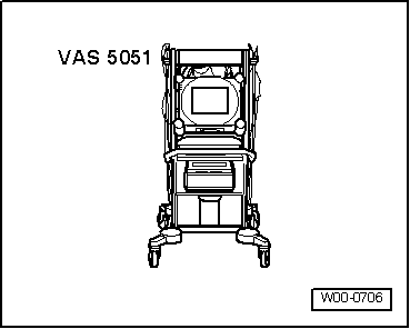
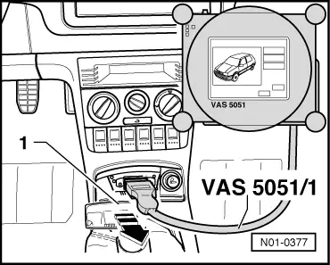
Connecting fault reader
 
W00-0706

All functions which could previously be performed with V.A.G 1551/1552 can also be performed with the new tester VAS 5051 in the operating mode vehicle self-diagnosis.

=> Operating instructions for Vehicle Diagnosis, Testing and Information System VAS 5051.

Special tools, workshop equipment, testers, measuring instruments and auxiliary items required

  • ◆ → VAS 5051 Vehicle Diagnosis, Testing and Information System
  • ◆ Diagnosis cable VAS 5051/1 or VAS 5051/3

Test conditions:

 
N24-0831
  • ◆ → Fuses No. 1, 3, 11, 15, 23, 30, 31, 32, 34, 36, 37, 39 and 40 must be OK.
  • ◆ The battery voltage must be at least 11.5 V.
  • ◆ Earth connection between engine (at bell housing) and body (under battery) OK.
  • ◆ Earth connection in plenum chamber OK.

Connecting VAS 5051

 
N01-0377
  • ‒ → Remove ash tray -1-.
  • ‒ Fit connector from diagnosis cable VAS 5051/1 or VAS 5051/3 to diagnosis connection.
  • ‒ Depending upon desired function:
    Switch ignition on
         or
    Start engine , Table "Selectable functions".

Selecting operating mode:

  • ‒ Press button on display for "Vehicle self-diagnosis".

Selecting vehicle system:

  • ‒ Press button "01 - Engine electronics" on display.

The control unit identification and coding are indicated on the display.

If the coding differs from the vehicle version:

  • ‒ Check control unit coding and, if necessary, code engine control unit => Page 24-124

Selecting diagnosis function:

All diagnostic functions available are indicated on the display.

  • ‒ Press button on display for desired function.

Notes:

The display zones in functions 04 - Basic setting or 08 - Read measured value block are shown from top to bottom.

The following test sequences are for fault reader V.A.G 1551.

Connecting V.A.G 1551

Special tools, workshop equipment, testers, measuring instruments and auxiliary items required

  • ◆ V.A.G 1551 Fault reader
  • ◆ V.A.G 1551/3 Cable

Note:

The vehicle system tester V.A.G 1552 can be used instead of the fault reader V.A.G 1551, however a print-out is not possible.

Work sequence

  • ‒ Connect fault reader V.A.G 1551 using cable V.A.G 1551/3.
  • ‒ Depending upon desired function:
    Switch ignition on
         or
    Start engine => Page 01-5 , Table "Selectable functions".

Notes:

  • ◆ If the display remains blank, check voltage supply for diagnostic connection according to fault finding programme:

=> Current flow diagrams, Electrical fault finding and Fitting locations

  • ◆ If the display does not indicate as described in the work sequence:

=> Fault reader operating instructions

  • ◆ If due to an input fault "Fault in the data transfer!" is displayed, pull wire off fault reader, reconnect and repeat work step.
 
→ Indicated on display:
V.A.G - SELF DIAGNOSIS     HELP
     1 - Rapid data transfer*
     2 - Flash code output*

* Appears alternately

  • ‒ Operate fault reader taking into account the information on the display:
  • ‒ Press key 1 for "Rapid data transfer".
  • ‒ Press keys 0 and 1 for address word "Engine electronics" and confirm entry with Q key.
 
→ On the display the control unit identification and coding are displayed, e.g.:
036906033A 1.6l/4V SIMOS3 00HS3148 ⇒
Coding 00031     WSC XXXXX
  • ◆ 036 906 033A = Part No. of the control unit (for up-to-date control unit versions see parts catalogue)
  • ◆ 1.6 ltr. = Engine displacement
  • ◆ 4V = 4 valves
  • ◆ SIMOS 3 = System designation
  • ◆ 00 = No. of changed adaption channels
  • ◆ HS = Manual gearbox (hand change)
  • ◆ 3148 = Programme level number
  • ◆ Coding 00031 = Control unit coding, coding variants of engine control unit => Page 24-127 .
  • ◆ WSC xxxxx = Workshop code from V.A.G 1551, of the workshop which carried out the last coding. (If the factory coding has not been changed, WSC 00000 appears)

Note:

Replace control unit if the control version displayed does not correspond to the vehicle

=> Page 24-121 .

An incorrectly coded engine control unit leads to:

  • ◆ Engine running faults (gear change jerks, load change jerks, etc.)
  • ◆ Increased fuel consumption
  • ◆ Increased exhaust gas emissions
  • ◆ Faults stored in fault memory which are not actually present
  • ◆ Functions will not be performed (Lambda regulation, activation of the activated charcoal filter system, etc.).
  • ◆ Reduced gearbox life

If the coding differs from the vehicle version, then:

  • ‒ Checking control unit coding => Page 24-124 ,
    coding engine control unit
  • ‒ Press ⇒key.
 
→ Indicated on display:
Rapid data transfer     HELP
Select function XXX
  • ‒ Further measures see repair procedures.

Fault memory > < Significance of exhaust emissions warning lamp