
Polo Mk3
|
Servicing front suspension
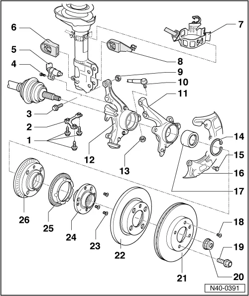
II - Assembly overview wheel bearing, suspension strut
|
 |
|
|
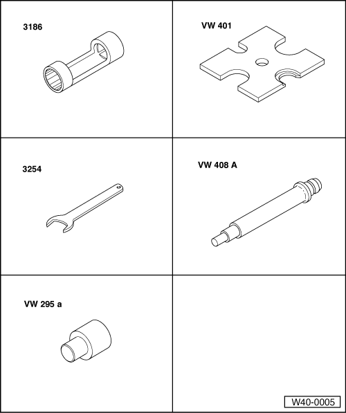
Special tools and workshop equipment required
|
 |
|
|
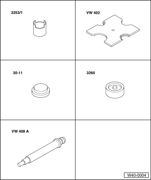
Special tools and workshop equipment required
|
 |
|
|
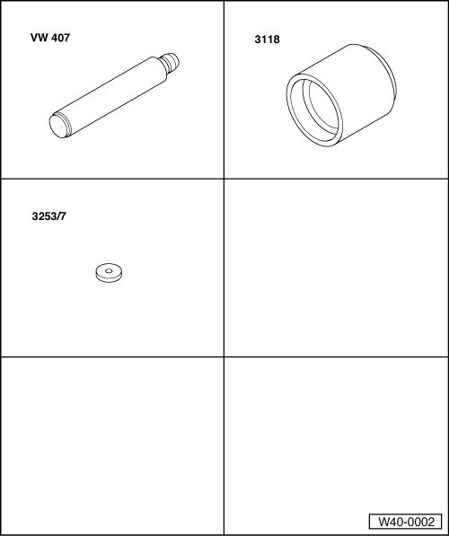
Special tools and workshop equipment required
|
 |
|
|
Notes:
|
|
|
|
|
|||||||||||
| |||||||||||
|
|||||||||
| |||||||||
|
|
|
|
|
|
 |
|
|
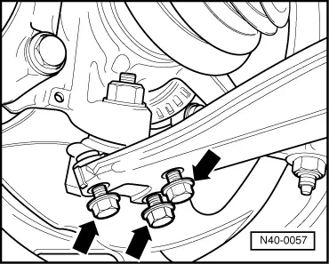
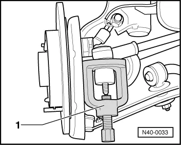
→ Fig.1 Separating ball joint/wishbone connection
|
 |
|
|
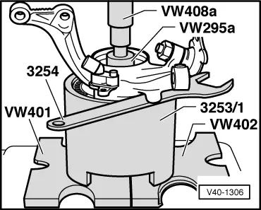
→ Fig.2 Pressing wheel hub out of wheel bearing housing |
 |
|
|
→ Fig.3 Pulling bearing race out of hub Remove speed sensor rotor if fitted (on vehicles with ABS). Only use puller with leg clamp e.g. Kukko 204-2 (commercial type). |
 |
|
|
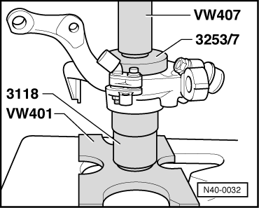
→ Fig.4 Pressing wheel bearing out of wheel bearing housing Fist remove securing ring. |
 |
|
|
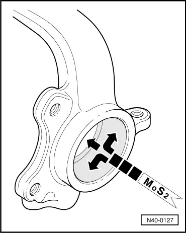
→ Fig.5 Coating hole surface with Molykote grease Use grease sachet from repair set. |
 |
|
|
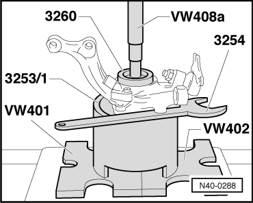
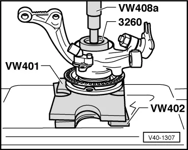
→ Fig.6 Pressing wheel bearing into wheel bearing housing
|
 |
|
|
→ Fig.7 Pressing hub into wheel bearing |
 |
|
|
→ Fig.8 Pressing track rod ball joint off steering arm
|