volkswagen Workshop Repair Guides

Volkswagen Workshop Service and Repair Manuals

Removing and installing radio/navigation system > < Electronic anti-theft system
Radio, telephone, navigation
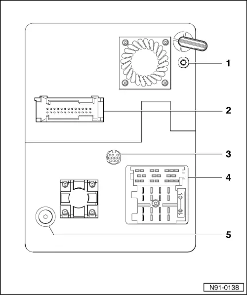
Radio/Navigations System (RNS) with multi-function display (MFD)
Connections on radio navigation system
 
N91-0138
  • Navigation system aerial connection
  • 26-pin connection for navigation sensors
    • Contact assignment =>page 91-53 .
  • RGB connection (Video)
    • This connection is not wired up.
  • Multi-pin connections I, II, III
    • Contact assignment => from page 91-53 .
  • Radio aerial connection

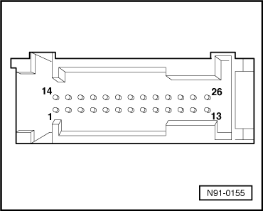
Contact assignment of 26-pin connector for navigation sensors

 
N91-0155

→ 26-pin connector

  •      4 -     Terminal 15 (ignition)
  •      5 -     Speed sensor output, left
  •      6 -     Navigation instructions Nf +
  •      13 -     CAN bus High
  •      17 -     Reversing light switch
  •      18 -     Speed sensor output, right
  •      19 -     Navigation instructions Nf -
  •      20 -     Navigation instructions Nf screen
  •      26 -     CAN bus LOW

Multi-pin connectors I, II, III contact assignment on rear of radio/navigation system

Multi-pin connector I, -T20- consists of 3 parts that are marked with different colours:

 
N91-0139

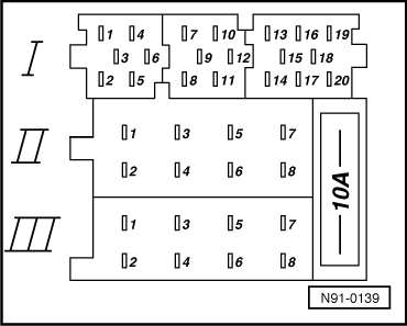
→ Multi-pin connector I, part 1, yellow

  •      1 -     Line Out rear left, LR
  •      2 -     Line Out rear right, RR
  •      3 -     Line Out, earth
  •      4 -     Line Out front left, LF
  •      5 -     Line Out front right, RF
  •      6 -     Switched positive for sound amplifier

Multi-pin connector I, part 2, green

  •      7 -     Telephone input signal, TEL+
  •      8 -     Second display, CLOCK
  •      9 -     Second display, DATA
  •      10 -     Second display, ENA
  •      11 -     Remote control, REM
  •      12 -     Telephone input signal, TEL-
 
N91-0139

→ Multi-pin connector I, part 3, blue

  •      13 -     CD changer, DATA IN
  •      14 -     CD changer, DATA OUT
  •      15 -     CD changer, CLOCK
  •      16 -     CD changer, terminal 30 voltage supply (+)
  •      17 -     CD changer, control signal
  •      18 -     CD changer, left and right channel, earth
  •      19 -     CD changer, left channel, CD/L
  •      20 -     CD changer, right channel, CD/R
 
N91-0139

→ Multi-pin connector II, -T8a-, 8-pin, brown

  •      1 -     Loudspeaker + rear right
  •      2 -     Loudspeaker - rear right
  •      3 -     Loudspeaker + front right
  •      4 -     Loudspeaker - front right
  •      5 -     Loudspeaker + front left
  •      6 -     Loudspeaker - front left
  •      7 -     Loudspeaker + rear left
  •      8 -     Loudspeaker - rear left
 
N91-0139

→ Multi-pin connector III, -T8-, 8-pin, black

  •      1 -     Gala (volume adaption)
  •      2 -     Telephone mute circuit
  •      3 -     Self-diagnosis/K wire
  •      4 -     Connection for ignition key controlled switching on and off (S contact)
  •      5 -     Anti-theft system control signal, SAFE
  •      6 -     Illumination (terminal 58b)
  •      7 -     Battery + (terminal 30)
  •      8 -     Battery - (terminal 31)

Removing and installing radio/navigation system > < Electronic anti-theft system