volkswagen Workshop Repair Guides

Volkswagen Workshop Service and Repair Manuals

Self-diagnosis for radio generation 10.99 > > < Self-diagnosis|Tools
Radio, telephone, navigation
Self-diagnosis
Connecting fault reader

Measures for rectifying commonly occurring faults on particular models

=> Technical Service Handbook

If faults occur in the sensors and components being monitored, they will be stored in the fault memory together with an indication of the type of fault.

A maximum of 4 faults can be stored simultaneously.

Sporadic faults are automatically cancelled if they are not repeated in next 50 engine starts.

The self diagnosis must be initiated at the commencement of fault finding and the stored information interrogated with the

Vehicle Diagnosis, Testing and Information system VAS 5051 or

Fault reader V.A.G 1551 or

Vehicle system tester V.A.G 1552.

The fault information displayed is used in conjunction with a fault table which has information on the possible fault causes for pin-pointed repair measures.

All functions which could previously be performed with V.A.G 1551/1552 can also be performed with the new tester VAS 5051 in the operating mode vehicle self-diagnosis.

 
N37-0341

=> Operating instructions for Vehicle Diagnosis, Testing and Information System VAS 5051.

Connecting VAS 5051

For vehicles up to ▸08.97

The self-diagnosis connection is located behind the shelf on the driver's side.

  • ‒ Open and unhook shelf on driver's side.
  • ‒ Fit connector from diagnosis cable VAS 5051/1 or VAS 5051/3 to diagnosis connection.
 
N02-0543

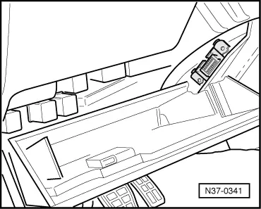
For vehicles 09.97 ▸

The self-diagnosis connection is located on the fuse strip in front left footwell

  • ‒ Remove cover in front of fuse strip
  • ‒ Fit connector from diagnosis cable VAS 5051/1 or VAS 5051/3 to diagnosis connection.
 
N02-0677

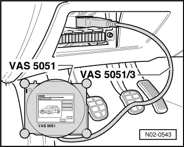
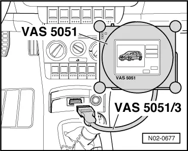
For vehicles 10.99 ▸

  • ‒ Remove ashtray insert -1-.
  • ‒ Fit connector from diagnosis cable VAS 5051/1 or VAS 5051/3 to diagnosis connection.
  • ‒ Switch on ignition.

Selecting operating mode:

  • ‒ Press button on display for "Vehicle self-diagnosis".

Selecting vehicle system:

  • ‒ Press button on display for vehicle system to be tested.

The control unit identification and coding are indicated on the display.

Selecting diagnosis function:

All diagnostic functions available are indicated on the display.

  • ‒ Press button on display for desired function.

Notes:

  • ◆ The display zones in functions 04 - basic setting or 08 - read measured value block are displayed from top to bottom.
  • ◆ The following test sequences are described for fault reader V.A.G 1551.

Connecting V.A.G 1551

Check prerequisites:

  • ◆ All fuses according to current flow diagram OK.
  • ◆ The battery voltage must be at least 9.5 V.

Work sequence

  • ‒ Connect fault reader V.A.G 1551 with cable V.A.G 1551/3.

Notes:

  • ◆ If the display remains blank, check V.A.G 1551 voltage supply according to current flow diagram.

=> Current flow diagrams, Electrical fault finding and Fitting locations binder

  • ◆ Additional operating information can be printed out depending on the programme by pressing the HELP key of V.A.G 1551.
  • ◆ In the operating mode 1 "Rapid data transfer" the function 00 "Automatic test sequence" can be carried out. Then all vehicle control units will be interrogated automatically.
  • ◆ The ⇒key is used for advancing the programme sequence.
  • ◆ The PRINT key is used for switching on the printer (warning lamp in key lights up).
  • ‒ Switch on ignition.
 
→ Indicated on display:
V.A.G - SELF DIAGNOSIS     HELP
     1 - Rapid data transfer*
     2 - Flash code output*

* Appears alternately

  • ‒ Operate fault reader taking into account the information on the display:
  • ‒ Press key 1 for "Rapid data transfer".
  • ‒ Continue self-diagnosis for vehicle system to be tested as described in "Performing self-diagnosis" => Contents

Self-diagnosis for radio generation 10.99 > > < Self-diagnosis|Tools