
Polo Mk4
| Assembly overview - fuel tank with attachments |

| 1 - | Securing clip |
| 2 - | Cap |
| 3 - | Seal |
| q | Renew if damaged. |
| 4 - | Securing bolt |
| 5 - | Tank flap unit |
| q | With rubber cup. |
| q | Removing and installing → General body repairs, exterior; Rep. Gr.55. |
| 6 - | Gravity valve |
| q | To remove valve unclip upwards out of support. |
| Check valve for through-flow. |
| q | Valve vertical: open. |
| q | Valve tilted 45 °: closed. |
| 7 - | Earth connection |
| q | Check for secure seating. |
| 8 - | Breather line |
| q | Check for secure seating. |
| 9 - | Active charcoal filter |
| q | Location: in front right wheel housing. |
| 10 - | 10 Nm |
| 11 - | Breather line |
| q | Clipped onto fuel tank. |
| q | Check for secure seating. |
| 12 - | 25 Nm |
| 13 - | Fuel tank |
| q | When removing, support using engine and gearbox jack -V.A.G 1383 A-. |
| q | Removing and installing → Chapter. |
| q | Fuel system must be bled if fuel tank is renewed → Chapter. |
| 14 - | Securing strap |
| 15 - | Breather line |
| q | Check for secure seating. |
| 16 - | Securing clip |
| q | Check for secure seating. |
| 17 - | Fuel filter |
| q | Installation position: arrow points in direction of flow. |
| q | Fuel system must be bled if fuel filter is renewed → Chapter. |
| 18 - | Supply line |
| q | Black |
| q | Check for secure seating. |
| q | To fuel rail. |
| 19 - | Seal |
| q | Renew if damaged. |
| 20 - | O-ring |
| q | Renew. |
| 21 - | Fuel pressure regulator |
| 22 - | 5 Nm |
| q | For fuel filter clamp. |
| 23 - | Seal |
| q | Renew if damaged. |
| q | When installing, insert seal dry into fuel tank opening. |
| q | Moisten with fuel only when installing flange. |
| 24 - | Fuel gauge sender |
| q | Removing and installing → Chapter. |
| q | Adjusting → Current flow diagrams, Electrical fault finding and Fitting locations. |
| 25 - | Fuel delivery unit |
| q | Removing and installing → Chapter. |
| q | Clean strainer if soiled. |
| q | Checking fuel pump → Chapter. |
| q | Note installation position on fuel tank → Fig.. |
| q | Fuel system must be bled if fuel delivery unit is renewed → Chapter. |
| 26 - | Return line |
| q | Blue |
| q | Clipped onto side of fuel tank. |
| q | Check for secure seating. |
| 27 - | Supply line |
| q | Black |
| q | Clipped onto side of fuel tank. |
| q | Check for secure seating. |
| 28 - | Union nut, 80 Nm |
| q | Remove and install using union nut tool -3217-. |
| 29 - | 10 Nm |
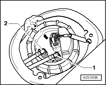
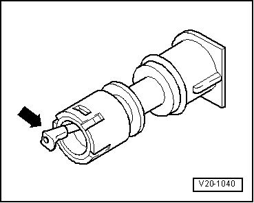
| 30 - | Breather valve |
| q | Checking → Fig.. |
| q | To remove pull locking latch lightly to inside -arrow- and pull valve out. |
 Note
Note
|
|