Polo Mk4
 Note
Note
|

| 1 - | Upper cover from mechanical distribution |
| 2 - | Indented belt |
| q | Before removal, note down direction of rotation |
| q | Check wear |
| q | Do not fold |
| q | Remove and install, adjust → Chapter. |
| 3 - | 10 Nm |
| q | Replace |
| 4 - | 25 Nm |
| 5 - | 100 Nm |
| 6 - | Valve command shaft gear |
| 7 - | Cube |
| q | With rotation sensor. |
| q | To tighten and loosen, use the support -T10051- |
| q | To remove use pulling device -T10052- |
| q | Remove and install → Chapter, remove and install valve command shaft |
| 8 - | Rear cover from mechanical distribution |
| 9 - | Sealing scoop |
| q | Replace when damaged |
| 10 - | Sensor Hall -G40- |
| q | For the valve command shaft position |
| q | For removal take out sealing scoop → Item on the rear of mechanical distribution protector |
| 11 - | Head screw |
| q | Observe sequence when loosing and tightening → Chapter, Remove and install head |
| q | before assembly place washers on the head → Item, → Item |
| 12 - | Head cover |
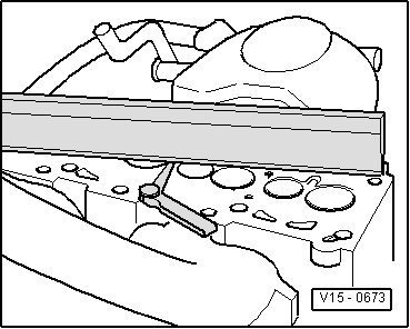
| q | Before installation, carefully clean head sealing surface with a clean cloth |
| 13 - | Pressure regulator valve |
| q | For carter vent device |
| 14 - | To the turbo-compressor |
| 15 - | Container cover |
| q | Replace joint if damaged |
| 16 - | Sealing scoop |
| q | Replace when damaged |
| 17 - | 10 Nm |
| q | Observe tightening sequence → Chapter, Head cover - remove and install |
| 18 - | Head cover joint |
| q | Replace when damaged |
| q | Before placing seal transitions with “AMV 174 004 01” → Chapter, Head cover - remove and install |
| 19 - | 20 Nm |
| 20 - | Suspension eyelet |
| 21 - | Unit-pump-injector |
| q | Remove and install → Chapter. |
| 22 - | 10 Nm |
| 23 - | -Central connection |
| q | For unit - pump -injector |
| 24 - | From power brake |
| 25 - | Vacuum pump |
| q | To power brake |
| q | Check → Chapter. |
| q | Remove and install → Chapter. |
| 26 - | Supply hose |
| q | From fuel filter. → Chapter, → Item |
| q | White or with white marking |
| q | Ensure firm fixing |
| q | Ensure with spring clamps |
| 27 - | Return hose |
| q | To fuel filter → Chapter, → Item |
| q | Blue or blue marking, respectively |
| q | Ensure firm fixing |
| q | Ensure with spring clamps |
| 28 - | Joint |
| q | Replace |
| 29 - | Screw |
| 30 - | Head |
| q | Remove and install → Chapter. |
| q | After replacement, fully replace cooling fluid |
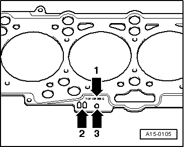
| 31 - | Head joint |
| q | Replace |
| q | Verify identification → Fig. |
| q | After replacing, fully replace cooling fluid |
| 32 - | Glower plug |
| q | 15 Nm |
| q | Check → Chapter. |
| 33 - | Tension pulley |
| 34 - | 20 Nm + 45 ° |
Note
|
|