volkswagen Workshop Repair Guides

Volkswagen Workshop Service and Repair Manuals

Valve command shaft seal - remove and install > < Valve command shaft - remove and install|Remove
Installation
Installation
  Note
   
t  
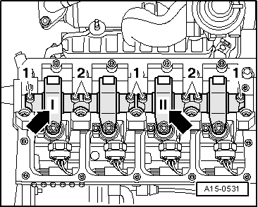
During installation of valve command shaft, cylinder 1 cams must be turned upwards.
t  Do not invert caps used (identify)
t  When installing valve command shaft ensure cap lugs are duly placed on bearing caps and head.
t  Before assembly, pay attention to bearing caps to ensure head screw washers are placed on head.
–  Lubricate valve command shaft contact surfaces.
–  Tighten bearings 2 and 4 caps alternately in a cross pattern with 8 Nm + 90 °
–  Install bearings 5, 1 and 3 caps and tighten with 8 Nm + 90 °
  Note
t  
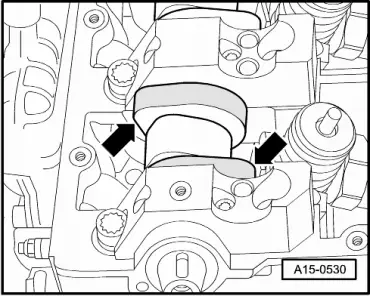
Seal bearings 1 and 5 separation surfaces with AMV 174 004 01 → Fig., → Fig..
t  Bearing 5 cap must align with head external ridge, otherwise it may cause tandem pump to leak.
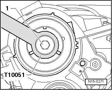
–  Assemble sealing ring for valve command shaft → Chapter.
  A15-0530
–  Assemble lever shaft and tighten initially internal fastening screws -2- and then the new external -1-, homogeneously in a crossing pattern. 20 Nm + 90 torque °
–  Place cube on valve command shaft.
  A15-0531
–  Tighten cube fastening screw -1-100 Nm torque.
–  Use counter-support -T10051-.
  N15-0271
–  Push command shaft gear over the cube.
  Note
Indented segment -arrow- of command shaft must be upwards.
–  Align command shaft in central position on oblong holes.
–  Insert fastening screws-1- manually, without play relative to the command shaft gear.
–  Block command shaft with pin -3359-.
–  Install indented belt, adjust → Chapter.
–  Install tandem pump → Chapter.
  Note
After assembly of new tappets, engine must not be started for about 30 minutes. Hydraulic offsetting elements must accomodate (otherwise, valves will interfere with pistons).
  N15-0275

Valve command shaft seal - remove and install > < Valve command shaft - remove and install|Remove