volkswagen Workshop Repair Guides

Volkswagen Workshop Service and Repair Manuals

Cylinder head - remove and install|Installation > < Cylinder head - remove and install
Operation sequence
Operation sequence
  Note
During the works, disconnect the Battery -A- earth wire. First, check if a code radio equipment is installed. If necessary, query anti-theft code beforehand.
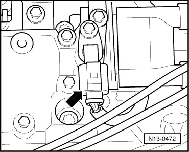
–  With the ignition turned off, disconnect the earth wire from the battery -A- .
–  Remove air filter body → Chapter.
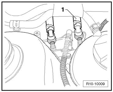
–  Disconnect cooling system lines from the engine cylinder head.
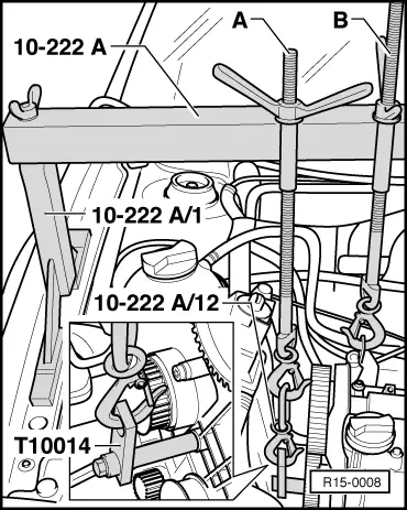
–  Screw lifting eyelets in the place of the cylinder head cooling system pipes. Tightening torque: 25 Nm
–  Release the front right wheel arch trim: → General body repairs, external; Rep. gr.66.
–  Remove toothed belt → Chapter.
–  Remove camshaft gear by immobilizing it using the Pin wrench -3036-.
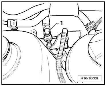
  WARNING
Fuel supply pipes are under pressure! Before disengaging hose connections, put a cleaning cloth on connection points. Then depressurize by carefully pulling the hose.
BAH engine
   
–  Loosen the fuel supply pipes (black) -1- (press the unlock key).
  R10-10008
BPA and CCRA engines
–  Loosen Magnetic valve I for activated charcoal reservoir -N80- on the intake manifold.
–  Close the pipes so as to avoid any dirt from coming into the supply system.
–  Disconnect or loosen the following components:
t  intake manifold vacuum line for the brake servo.
t  the fitting connector for the Ignition transformer -N152- and the Throttle valve module -J338-.
t  fitting connectors for injection valves.
t  the fitting connector for the Engine speed sensor -G28- and Intake manifold pressure sensor -G71- with Air intake temperature sensor -G42-.
t  the double-sided connector for the Knock sensor 1 -G61- (behind the block ).
t  fitting connector for the Coolant temperature sensor -G62- and Oil pressure switch -F1-.
  R10-10009
–  Disconnect the 3-pole connector for the Sensor Hall -G40--arrow-.
–  Fully remove the fuel distributor with all injectors → Chapter.
–  Open and close the coolant expansion tank cap to depressurize the cooling system once more.
–  Drain cooling system → Chapter.
–  Remove the water pump together with the mechanical distribution rear cover → Chapter.
–  Remove the clip on the thermostat housing, which holds the cooling system tube on the pump.
–  Remove the thermostat body from the engine cylinder head.
–  Disconnect all connection, cooling system, vacuum and suction hoses from the engine cylinder head.
–  Disconnect exhaust tube from the exhaust manifold.
–  Loosen the oil dipstick guide tube from intake manifold.
  N13-0472
–  Then, raise the engine a little bit with the aid of device -B- .
  Note
Since the lifting eyelet is screwed to the engine cylinder head, an additional support must be secured to the cylinder block to support the engine.
–  Screw, as indicated, the Lock -T10109- into the threaded hole in the water pump area on the cylinder block. Tightening torque: 20 Nm
–  Slightly raise the engine with the second threaded part -A- until the threaded part -B- is relieved.
–  Remove threaded part -B-.
  R15-0008
–  Loosen the engine cylinder head bolts in the indicated sequence and remove them.
–  Remove head fastening screws.
–  Remove the engine cylinder head carefully.
  N15-0026

Cylinder head - remove and install|Installation > < Cylinder head - remove and install