
Polo Mk4
 Note
Note
|

| 1 - | Piston |
| q | Check → Fig. |
| q | Mark assembly position and correspondence to respective cylinder |
| q | Piston head -arrow- must indicate pulley direction |
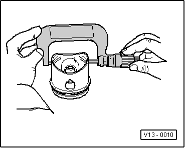
| q | Install with segment ring compressor |
| 2 - | Piston pin |
| q | If applied for heavy duties, heat pistons at 60 °C |
| q | with 10-206: remove and install |
| 3 - | Piston pin retaining ring |
| 4 - | Rod |
| q | Replace only set |
| q | Mark correspondence to cylinder -A- |
| q | Assembly position: Marks -B- must point toward steering wheel |
| q | Axial gap piston/rod 0.20 to 0.40mm Wear limit 0.50 mm |
| 5 - | Cap |
| q | Observe assembly position |
| q | Do not change used caps |
| q | Place caps centered |
| q | Measure radial gap with Plastigage: New: 0.010...0.057 mm Wear limit: 0.091 mm When measuring radial gap, do not turn crank shaft |
| 6 - | Engine block |
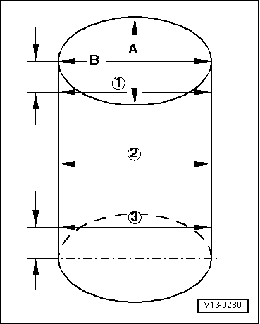
| q | Check cylinders diameter → Fig. |
| q | Pistons and cylinders specifications → Chapter. |
| 7 - | Rod covers |
| q | Observe assembly position |
| q | Rod covers may only be placed in one position and with corresponding rod |
| 8 - | Rod bolt, 20 Nm + 90 ° |
| q | Replace |
| q | Lubricate thread and support surface |
| q | To measure radial gap, tighten at 20 Nm, without angle torque |
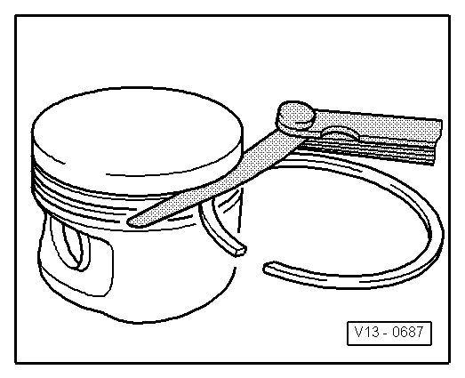
| 9 - | Oil scraper rings |
| q | Remove and install carefully, manually, oil scraper rings formed by 3 parts |
| q | Indication “TOP” must point toward piston head |
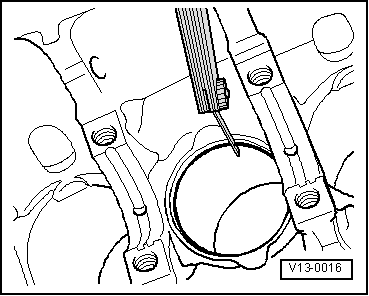
| q | Check interpoint openings of segment rings → Fig. |
| q | Check ring gap of ring on piston duct → Fig. |
| 10 - | Compression segment rings |
| q | Openings moved in 120 ° |
| q | Remove and install segment rings using ring pliers |
| q | Indication “TOP” must point toward piston head |
| q | Check interpoint gaps of segment rings → Fig. |
| q | Check ring gap of ring on piston duct → Fig. |
|
|
| Segment ring | New part Limit wear |
| 1. Compression segment ring | 0.15 to 0.30 1.0 mm |
| 2. Compression segment ring | 0.30 to 0.50 1.0 mm |
| Oil scraper ring | 0.15 to 0.30 1.0 mm |
|
|
| Segment ring | New part Limit wear |
| 1. Compression segment ring | 0.040 to 0.075 0.150mm |
| 2. Compression segment ring | 0.020 to 0.075 0.150mm |
| Oil scraper ring | 0.010 to 0.176 0.186mm |
|
|
Note
|
|