volkswagen Workshop Repair Guides

Volkswagen Workshop Service and Repair Manuals

Heat exchanger - remove and install > < Additional heating resistanceZ35
Additional heating resistanceZ35 - check
Additional heating resistance -Z35- - check
Special tools and workshop equipment required
t  Portable multimeter or VAG 1526C -EQ 7318- or Portable multimeter or EQ 7318 -VAG 1526C- or Multimeter -VAG 1715-
t  Current loop diagram
t  Auxiliary measuring cable set -VAG 1594C-
t  Digital potentiometer (included in VAG 1594C) -VAG 1630-
t  Diagnosis, Measurement and Information System -VAS 5051- or Diagnosis, Measurement and Information System -VAS 5052- or later equipment.
Checking conditions:
l  Intake air temperature below 19°C.
l  Coolant temperature below 80°C.
l  Cabin temperature at 20°C.
l  Battery voltage greater than 11 V.
l  Alternator charge equal to or less than 50% (DF terminal).
l  Engine speed regime superior to 450 rpm.
l  Control button for ventilation level in position 4.
l  Control button for internal temperature in maximum heating position.
Checking sequence:
If the intake temperature and coolant values specifications are not achieved, carry out the following checks.
The intake air temperature sensor and the intake manifold pressure sensor are housed in the same compartment in the intake manifold.
   
–  Connect the Digital potentiometer (included at VAG 1594C) -VAG 1630- to the Intake manifold temperature sensor -G72- connector between contacts -1- and -4-.
  A24-0094
Rated values, check the diagram.
-Position A- represents the resistance values for temperatures ranging between 0 and 50°C; -position B- represents the values for temperatures ranging between 50 and 100°C.
Sample reading:
t  10 ℉ corresponds to a resistance of 3500...4000 Ω.
t  80 ℉ corresponds to a resistance of 275...375 Ω.
–  Disconnect connector of Coolant temperature sensor -G62- → Engine; Rep. gr.19.
  N80-0326
–  Connect the Digital potentiometer (included at VAG 1594 C) -VAG 1630- to the Coolant temperature sensor -G62- connector between contacts -1- and -2-.
  N24-1026
Rated values, check the diagram.
-Position A- represents the resistance values for temperatures ranging between 0 and 50°C; -position B- represents the values for temperatures ranging between 50 and 100°C.
Sample reading:
t  40°C corresponds to a resistance of 1000....1500 Ω.
t  80 ℉ corresponds to a resistance of 275...375 Ω.
–  Connect Multimeter -VAG 1715- with the electric caliper to the thermal element power cable of the Additional heating resistance -Z35-.
  N80-0327

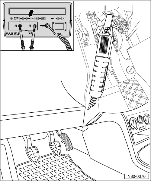
–  Set the Multimeter -VAG 1715- for verification in amperes.
10 seconds after the engine has been turned on, the heating element for the Additional heating resistance -Z35- is released by Control unit of the direct Diesel injection system -J248-. The three thermal elements are gradually switched on and off through the engine command unit relay.
–  Start the engine and leave it at idling speed.
Switch off air conditioning, if present.
In the checking conditions defined, the Additional heating resistance -Z35- starting current is equal or superior to approximately 38.9 A. After a heating-up phase of approximately 10 minutes of the Additional heating resistance -Z35- the current consumption will drop to 31.6 A. If the amount decreases by 10 A or more, check the cables according to the electric diagram.
   

If no fault is found in the cables:
–  Replace the Additional heating resistance -Z35- → Chapter.
–  Erase the fault memory → Vehicle diagnostic tester.
   

Heat exchanger - remove and install > < Additional heating resistanceZ35