
Polo Mk4
|

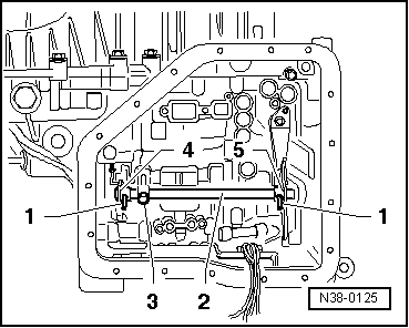
| 1 - | Automatic transmission control valve assembly |
| q | For selector axle |
| q | Disassemble → Fig. |
| q | Couple → Fig. |
| 2 - | Selection axle |
| q | Disassemble and assemble → Fig. |
| q | Avoid beating the axle in the axial direction when transporting the transmission; it could cut the screw -3- |
| 3 - | Screw, 10 Nm |
| q | Fasten the selection axle to the transmission case |
| 4 - | Spring for command part |
| q | Do not bridge |
| 5 - | Screw, 5 Nm |
| 6 - | Command part |
| 7 - | Adapter sleeve |
| q | For command part |
| q | Disengage it with a punch |
| q | Fit once the command part is placed → Fig. |
| 8 - | Adapter sleeve |
| q | For the connecting rod -9- |
| q | Disengage it with a punch |
| q | Fit once the command part is placed → Fig. |
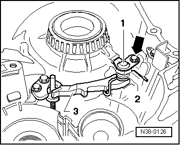
| 9 - | Connecting rod |
| q | Assemble with the gear lever -10- before assembling it in the selection axle |
| 10 - | Gear lever |
| q | Place along with the connecting rod in the selection axle |
| 11 - | Screw, 27 Nm |
| 12 - | Support plate |
| q | For the gear lever |
| 13 - | Screw, 5 Nm |
| 14 - | Cover |
| q | Strengthens the retaining lever axle |
| 15 - | Axle for retaining lever |
| q | It can be disassembled and assembled manually |
| 16 - | Recoil spring |
| q | Disassemble and assemble → Fig. |
| 17 - | Retaining lever |
| q | Disassemble and assemble → Fig. |
|
|
|
|
|
|