volkswagen Workshop Repair Guides

Volkswagen Workshop Service and Repair Manuals

Installing control unit and hydraulic unit > < Connecting brake lines from brake master cylinder to hydraulic unit
Removing control unit and hydraulic unit
Special tools and workshop equipment required
   
t  Torque wrench -V.A.G 1331-
  W00-0427
t  Brake pedal depressor -V.A.G 1869/2-
  W00-0679
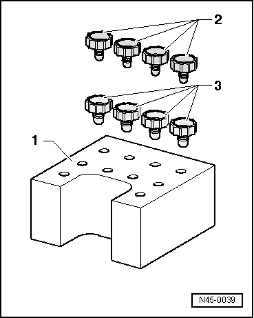
Sealing plugs repair kit, Part No. 1H0 698 311 A
Location:
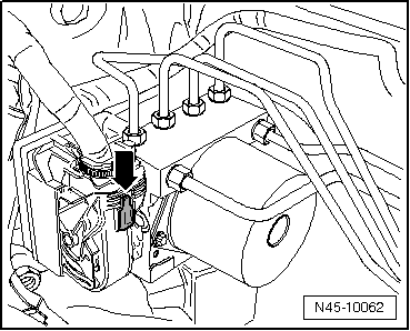
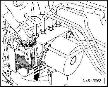
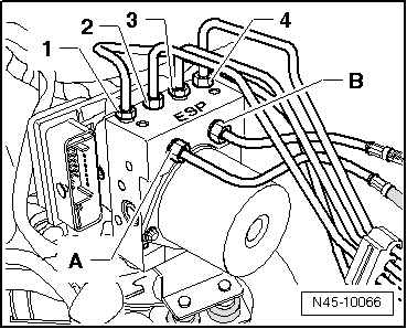
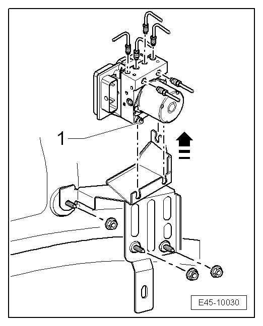
The control unit is bolted to the hydraulic unit and is located on right in the engine compartment.
  WARNING
Do not bend the brake lines in the area of the hydraulic unit!
Removing:
–  Read out and note the existing control unit code.
–  Note or request radio code on vehicles with coded radio if necessary.
–  Disconnect battery → Electrical system; Rep. gr.27.
Additional work on following engines:
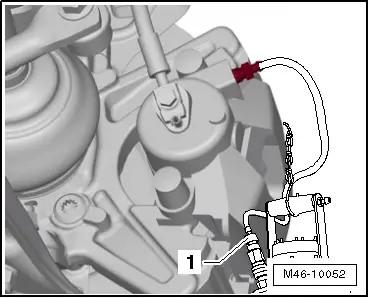
4-cyl. injection engine, toothed belt drive:
–  Pull hose off non-return valve to camshaft housing.
–  Remove intake hose and pull air filter housing upwards off pivot pins → 4-cyl. injection engine, toothed belt drive; Rep. gr.24.
–  .
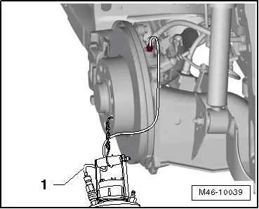
4-cylinder diesel engine (1.6 l engine, common rail):
–  Remove wiper arms → Electrical system; Rep. gr.92.
–  Remove plenum chamber cover → General body repairs, exterior; Rep. gr.50.
–  Pull engine cover panel up out of brackets.
  N45-0039
–  Disconnect all connectors for electrical wires -1 to 4- to diesel particulate filter and to lambda probe.
–  Then remove bracket along with connectors from plenum chamber bulkhead and lay to side.
–  Remove intake hose and air filter housing.
–  Take engine control unit out of bracket and lay to side.
–  Remove bracket for engine control unit.
–  Remove insulation from plenum chamber bulkhead.
–  Remove plenum chamber bulkhead → General body repairs, exterior; Rep. gr.50.
Continuation for all models:
  N26-10416
–  Press red locking slide -arrow- down.
  N45-10062
–  Release control unit connector -arrow - and pull off forwards.
  N45-10063
–  Apply brake pedal depressor -V.A.G 1869/2-.
  A44-0007
–  Connect bleed bottle bleed hose -1- to bleed valve of front left brake caliper.
–  Open bleed valve.
  M46-10052
–  Connect bleed bottle bleed hose -1- to bleed valve of rear left brake caliper/wheel brake cylinder.
–  Open bleed valve.
–  Depress brake pedal at least 60mm using brake pedal depressor -V.A.G 1869/2-.
–  Close front left and rear left bleeder valve.
–  Do not remove brake pedal depressor -V.A.G 1869/2-.
–  Place sufficient lint-free cloths under the control unit and hydraulic unit.
Ensure no brake fluid gets onto contacts.
–  Mark brake lines from hydraulic unit -A and B- to brake master cylinder.
  M46-10039
–  Then unscrew brake lines from hydraulic unit and from brake master cylinder, unclip from retainers and lay to side.
–  Immediately seal brake lines and threaded holes with seal plugs from repair set Part No. 1H0 698 311 A.
–  Mark remaining brake lines (to brake calipers) -1 to 4-, unscrew from hydraulic unit and seal.
–  Loosen 3 hexagon nuts -1- of rubber damper mountings.
  N45-10066
–  The cap nut (on side at top) must be unscrewed to height of stud shoulder, otherwise the removal is not possible.
–  Pull hydraulic unit with control unit upwards out of bracket.
–  If necessary, loosen hexagon nuts of bracket and remove bracket.
  E45-10030

Installing control unit and hydraulic unit > < Connecting brake lines from brake master cylinder to hydraulic unit