
Polo Mk5
| Assembly overview - removing and installing selector cables |
 Note
Note| t | Lubricate bearing positions and sliding surfaces. |
| t | Allocate grease using → Electronic parts catalogue (ETKA). |

| 1 - | Gear selector cable |
| q | Connect to cable end-piece → Item |
| q | Installation position → Chapter |
| q | From 06.06, modified attachment to gear lever inside selector mechanism → Item |
| 2 - | Gate selector cable |
| q | Connect to cable end-piece → Item |
| q | Installation position → Chapter |
| q | From 06.06, modified attachment to gate selector lever inside selector mechanism → Item |
| 3 - | Securing clip |
| q | Always renew |
| q | Discontinued in gearbox mechanisms from 06.06 → Chapter |
| 4 - | Selector housing |
| 5 - | Securing clip |
| q | Always renew |
| q | Do not damage cables when removing |
| 6 - | Hexagon bolt, 25 Nm |
| q | Qty. 3 |
| q | For cable support bracket |
| 7 - | Cable support bracket |
| q | May be made from plastic or metal |
| 8 - | Grommet |
| q | Cable support bracket mounting on gearbox |
| 9 - | Spacer |
| 10 - | Cable end-piece |
| q | After installing, adjust selector mechanism → Chapter |
| q | For gate selector cable to relay lever |
| q | Through 10.04 - always renew after removing from relay lever |
| q | From11.04 with end-to-end holes. |
| q | From this date, not necessary renew |
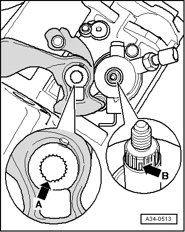
| q | For metal relay lever from this date, secured with securing clip → Anchor |
| q | From 12.06, fitted in conjunction with plastic relay lever → Fig. |
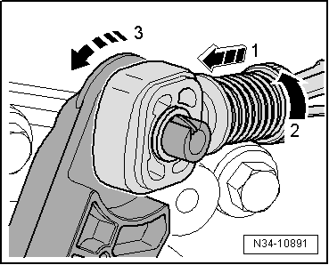
| q | Removing from plastic relay lever → Fig. |
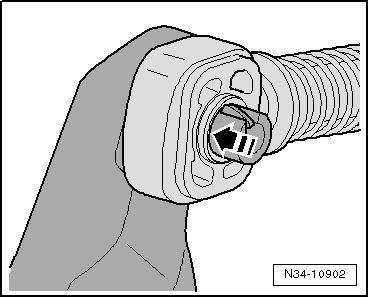
| q | Pressing onto plastic relay lever → Fig. |
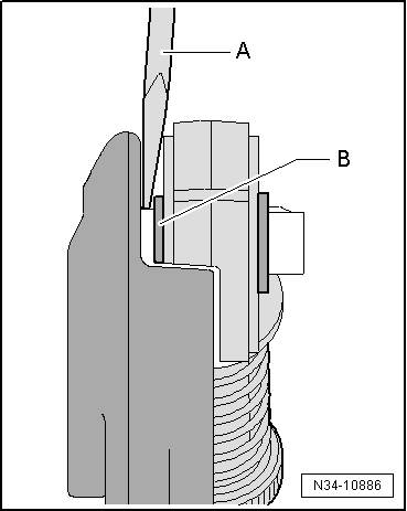
| q | Allocation → Fig. |
| 11 - | Cable end-piece |
| q | After installing, adjust selector mechanism → Chapter |
| q | For gear selector cable to gearbox selector lever |
| q | Through 10.04 - always renew after removing from gearbox selector lever |
| q | From 11.04 with end-to-end holes. |
| q | From this date, not necessary renew |
| q | Secured with securing clip → Anchor |
| q | Allocation → Fig. |
| 12 - | Relay lever |
| q | Installation position → |
| q | After installing, adjust selector mechanism → Chapter |
| q | May be made from plastic or metal |
| q | Metal relay lever is mounted in 2 bushes and secured with a securing clip → Chapter |
| q | Always renew securing clip |
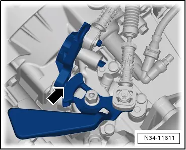
| q | From 12.06, plastic relay lever |
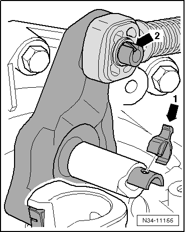
| q | Remove and install plastic relay lever together with cable end-piece → Fig. |
| q | Bearing bushes and securing clip not required for plastic relay lever |
| 13 - | Shoe |
| 14 - | Self-locking hexagon nut, 25 Nm |
| q | Always renew |
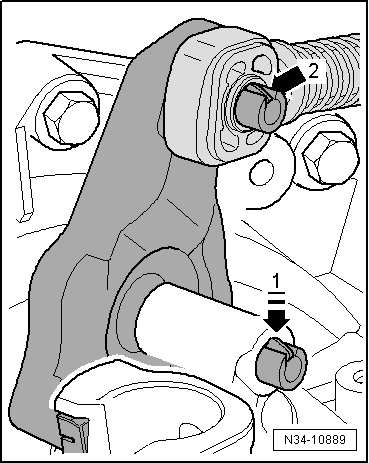
| 15 - | Gearbox selector lever |
| q | Can be renewed with the selector mechanism installed |
| q | Installation position → |
| q | Installing → Fig. |
| q | After installing, adjust selector mechanism → Chapter |
|
|
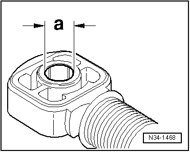
| Cable end-piece for | Dimension „a“ |
| Gear selector cable to gearbox selector lever | 10 mm |
| Gate selector cable to metal relay lever | 8 mm |
| Gate selector cable to plastic relay lever | 10 mm |
|
|
|
|
|
|
|
|
Note
|
|
|
|
|
|