| –
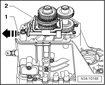
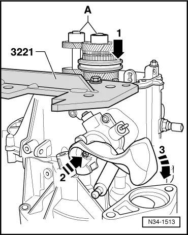
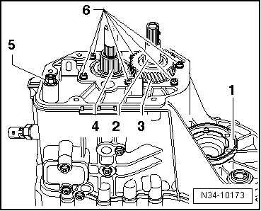
| Press out input shaft, output shaft with bearing mounting, selector mechanism (selector forks) and reverse gear together. |

Note | t
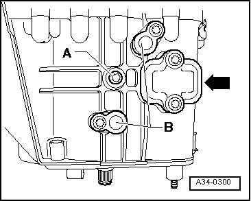
| Position gearbox housing so that dowel sleeves in the gearbox will not be damaged. |
| t
| When pressing out, get help from second mechanic to ensure components do not fall out. |
| –
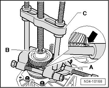
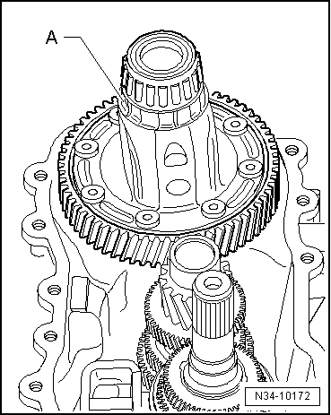
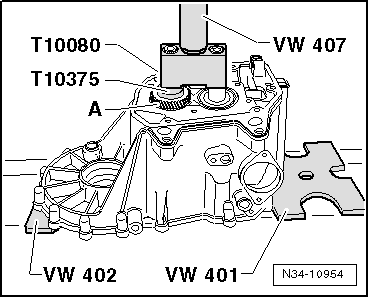
| Press input and output shafts, together with gear wheel for 5th gear, off deep groove ball bearing → Fig.. |
| –
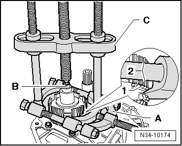
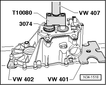
| Press input and output shafts, without gear wheel for 5th gear, off bearing mounting with deep groove ball bearing → Fig.. |
|
|
|