volkswagen Workshop Repair Guides

Volkswagen Workshop Service and Repair Manuals

Functional check > < Specified torques
Adjusting selector mechanism
Special tools and workshop equipment required
   
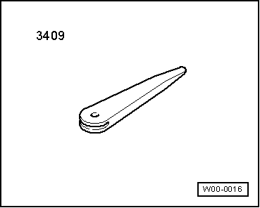
t  Removal wedge -3409-
  W00-0016
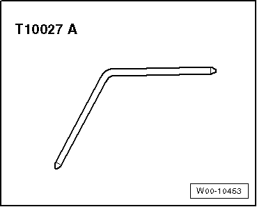
t  Locking pin -T10027 A-
  Note
t  The following points are essential to ensure correct adjustment of selector mechanism:
t  Moving parts of operating elements and elements transferring force must be in proper condition.
t  Selector mechanism must move freely.
t  Gearbox, clutch and clutch mechanism must also be in proper condition.
l  Gearbox must be in neutral.
l  Angled rod for fixing selector shaft and securing mechanism for gear selector cable and gate selector cable must be accessible.
–  Remove air filter housing if it blocks access to angled rod for fixing selector shaft and to securing mechanism for gear selector cable and gate selector cable → Rep. gr.23 or → Rep. gr.24.
  W00-10453
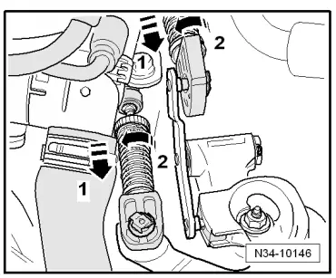
–  Pull locking mechanisms on gate selector cable and gear selector cable end-pieces forward to stop -direction of arrow 1- and then turn to left to lock -direction of arrow 2-.
  N34-10146
Secure selector shaft as follows:
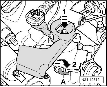
–  Press selector shaft down -direction of arrow 1-.
–  While pressing selector shaft down, turn angled rod -A- in -direction of arrow 2-. Press it simultaneously and carefully inwards until it engages in the selector shaft.
–  Remove gaiter and any noise insulation from frame for centre console using removal wedge -3409- → Chapter.
–  If noise insulation is present, remove it.
Now secure gear lever as follows:
–  Select neutral using gear lever.
  N34-10319
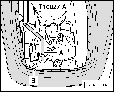
–  Guide locking pin -T10027 A- through hole -A- into hole -B-.
  N34-10814
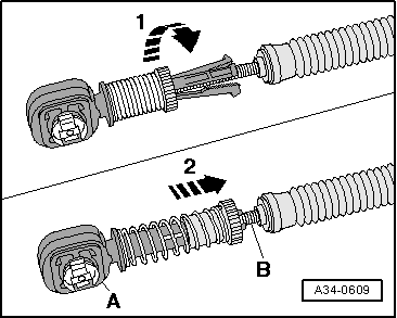
–  Check that gate and selector cables -B- are inserted, free of tension, into locking devices -A-.
–  Now turn locking mechanisms on gear selector cable and gate selector cable end pieces clockwise to stop -direction of arrow 1-.
The spring presses the locking mechanism into original position -direction of arrow 2-.
  A34-0609
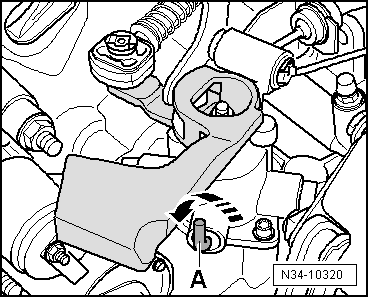
–  Now turn angled rod -A- back to original position -direction of arrow-.
  Note
The angled rod -A- must be pressed out of selector housing to stop and point straight up.
  N34-10320
–  Pull locking pin out of holes -A- and -B-.
–  If noise insulation was present, install it.
–  Press gaiter into console.
–  Check that selector shaft moves freely.
–  If removed, install complete air filter housing → Rep. gr.23 or → Rep. gr.24
  N34-10814

Functional check > < Specified torques