
Polo Mk5
| Dismantling and assembling output shaft |

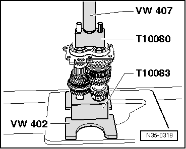
| Special tools and workshop equipment required |
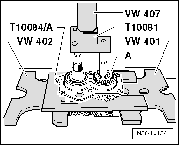
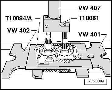
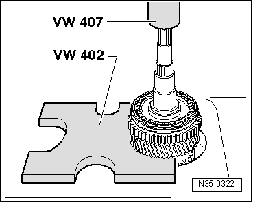
| t | Pressure plate -VW 402- |
| t | Press tool -VW 407- |
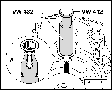
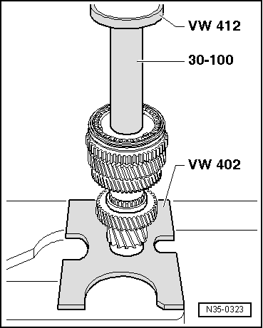
| t | Press tool -VW 412- |
| t | Tube -VW 415 A- |
| t | Thrust piece -VW 432- |
| t | Drift sleeve -30 - 100- |
|
|
|
|
|
|
|
|
|
|
|
|
 WARNING
|
|
|
|
|
|
|
|
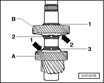
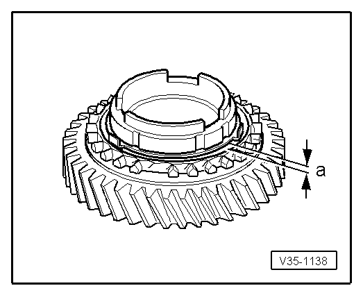
| Gap „a“ | Installation dimension | Wear limit |
| 1st and 2nd gears | 0.75 … 1.25 mm | 0.3 mm |
|
|
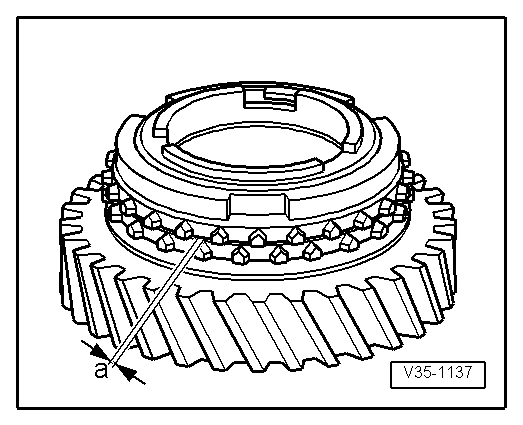
| Gap „a“ | Installation dimension | Wear limit |
| 1st and 2nd gears | 1.2 … 1.8 mm | 0.5 mm |
|
|
|
|
|
|
|
|
|
|
|
|
|
|
|
|
|
|