volkswagen Workshop Repair Guides

Volkswagen Workshop Service and Repair Manuals

Removing gearbox; Polo 2010 ?, 1.4 l - 132 kW petrol engine > < Removing gearbox; Polo 2010 ?, 1.4 l - 63 kW petrol engine
Removing gearbox; Polo 2010 ►, 1.6 l - 66 kW diesel engine
   
Removing gearbox; Polo 2010 ►, 1.6 l - 66 kW diesel engine
Special tools and workshop equipment required
t  Support bracket -10 - 222 A-
t  Adjustment plate -3282/59-
t  Socket -T10035-
t  Socket -T10061-
t  Gearbox support -3282-
t  Insert tool, 18 mm -T10179-

   
t  Socket -T10107 A-
t  Shackle -10 - 222 A /12-
t  3 tensioning belts -T10038-
t  Adapter -10 - 222 A /18-
t  Engine and gearbox jack -V.A.G 1383 A-

Brief description
The gearbox is removed downwards separately, without engine. »From above«
Remove battery, air filter and starter.
»From below«:
Remove noise insulation beneath engine, front left wheel housing liner and subframe with pendulum support. Secure drive shafts so that they do not disrupt removal. However, leave them on the suspension struts. The gearbox is removed downwards separately, without engine.
Subframe must be secured.
Removing:
–  Raise vehicle. All 4 supports of lifting platform must be at same height.
–  Move selector lever to position »P« position.
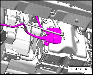
–  Remove engine cover from cylinder head.
   
–  Remove battery and -battery tray- → Rep. gr.27.
–  Remove complete air filter housing → Rep. gr.24.
  N34-11366
–  Remove battery carrier.
  N37-10427
–  Later, during installation, please check whether both breather caps are seated on gearbox.
–  Remove starter → Electrical system; Rep. gr.27.
During removal, it is recommended to remove the lower bolt first.
  N30-10235
These tools are appropriate for this.

   
–  Remove selector lever cable from ball head, remove securing clip.
A securing clip which has been removed is not allowed to be installed again. The clip will have lost its internal tension and so it might fall off.
–  Therefore, when installing, always use a »new« securing clip.
Remove cable with great care from cable support bracket on gearbox. Do not bend it.
Cable may also be pushed slightly backwards out of cable support bracket and removed later when gearbox is lowered. But then observe cable when lowering gearbox.
–  Remove charge air line to access upper connecting bolts of gearbox → Rep. gr.21.
–  Now remove all upper connecting bolts between engine and gearbox.
  N34-11373
–  Release mechatronic unit connector by pulling and pull off connector.
–  Remove noise insulation → Rep. gr.50.
–  Remove left front part of wheel housing liner → Rep. gr.66.
  N34-11386
–  Remove all retainers and brackets from front of gearbox.
–  If fitted, remove radiator fan control unit -J293- with retainer from longitudinal member.
–  If fitted, remove power steering hydraulic unit from longitudinal member and secure with wire.
–  Remove subframe with pendulum support and secure → Rep. gr.40.
  N34-10966
–  If fitted, remove the heat shield over the right-hand drive shaft. Tightening torque → Rep. gr.40
–  Unbolt both drive shafts from gearbox.
  N34-11369
Secure both drive shafts to suspension struts using tensioning straps -T10038-.
The surface protection of the shafts must not be damaged. Plastic cable ties or a pair of tensioning straps -T10038- are therefore very good for this.
–  Swing left drive shaft into wheel housing onto longitudinal member. This will keep the shaft out of the way during further work.
  N37-10433
–  Remove right flange shaft of gearbox using socket -T10107 A-.
Bolt has a 6 mm hexagon socket. Bolt can also be removed and installed with socket -V.A.G 1669-.
  N34-11389
–  Screw 2 bolts into flange and counterhold flange shaft with a lever in order to remove and install flange shaft.
–  Remove flange shaft with compression spring.
–  Close opening in drive shaft using a suitable plug.
–  To install flange shaft, if necessary press against gearbox with a lever and screw in bolt.
Torque setting 30 Nm
  A34-0615
–  In some vehicles, there is still another small cover plate on intermediate plate. It is above right drive flange. Remove this plate.
–  If there are hose and cable connections in area of engine support eyes for support bracket -10-222A-, remove these now.
–  If fitted: remove filler pieces from upper edges of both wings.
  N34-11427
–  Support engine and gearbox, but do not raise.
  N34-11428
Remove 3 bolts from bracket.
2 bolts vertical, 1 bolt horizontal on top of gearbox.
  N34-11429
–  Then lower engine and gearbox slightly using spindle of support bracket -10 - 222 A- until lower bolts of bracket can be removed.
In many cases, the spindle does not need to be lowered further for the later removal of the gearbox.
–  Set up gearbox support -3282- with adjustment plate -3282/59-.
  N34-11426
–  Move engine and gearbox jack -V.A.G 1383 A- under gearbox and support gearbox. Do not raise.
–  Position plate of pin under gearbox housing, not under mechatronic unit.
–  Screw a pin into »rear« hole for pendulum support.
The gearbox is separated from the engine in this position.
–  Remove remaining engine/gearbox connecting bolts.
–  Press gearbox off engine, »observing selector lever cable« and lower gearbox.
  N34-11392
In some cases, there are retainers on the front of the gearbox.
–  Remove retainers.
If a »new« gearbox is being fitted, these retainers are not present on »new« gearbox.
Gearbox with flange shafts, torque setting → Chapter
Bolt has a 6 mm hexagon socket. Bolt can also be removed and installed with socket -V.A.G 1669-.
  N34-11393
–  Renew needle bearing in crankshaft → Rep. gr.13.
–  Install right flange shaft again.
Torque setting 30 Nm
Installing gearbox → Chapter.
  N34-11460

Removing gearbox; Polo 2010 ?, 1.4 l - 132 kW petrol engine > < Removing gearbox; Polo 2010 ?, 1.4 l - 63 kW petrol engine