| t
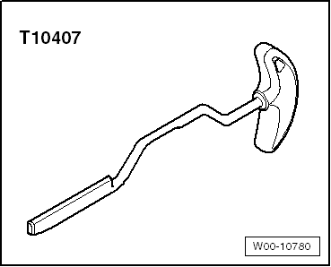
| Assembly lever -T10407- |
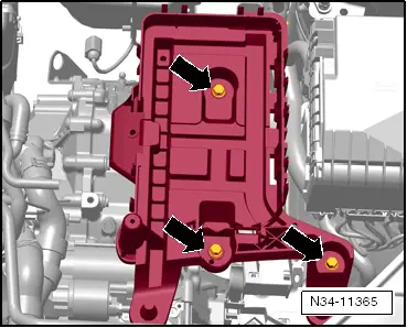
| In order to remove the mechatronic unit, sufficient space must be available in front of the gearbox. Depending on the vehicle, parts must be removed which do not have anything to do directly with the gearbox. For example, the air filter housing, if present, charge air lines or coolant lines. In Polo 2010, for example, radiator fan control unit -J293- with retainer. |
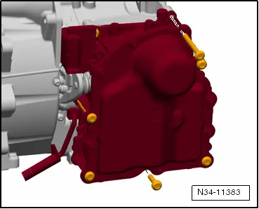
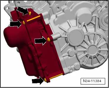
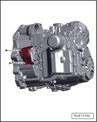
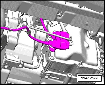
| Any retainers fitted to the bolts in the cover of the mechatronic unit must be removed. |
| Tester moves all gear actuators »into neutral«. |
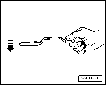
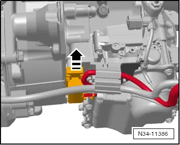
| In this position, insert assembly lever -T10407- between clutch lever and gearbox housing. This makes it possible to remove load from plungers of mechatronic unit so that they may be removed by hand from cups of engaging levers. |
| Mechatronic unit can be removed and inserted. When installing, make sure clutch plungers are correctly seated in cup of engaging levers. |
| Therefore, please follow description below step by step. |

Note | t
| The clutch is self-adjusting. Shocks can have an effect on this adjusting device. Even if the mechatronic unit has been removed, the »sudden removal« of the assembly lever -T10407- from under the engaging levers can have a negative effect on the adjusting mechanism. |
| t
| In order to remove the mechatronic unit, sufficient space must be available in front of the gearbox. In some vehicles, parts must be removed which do not have anything to do directly with the gearbox. Remove any charge air lines or coolant lines that may be present. |
| t
| Any retainers fitted to the bolts in the cover of the mechatronic unit are also removed. |
| t
| A »new« mechatronic unit is correctly filled with oil. |
| t
| Do not drain oil. A »removed« mechatronic unit is sent back with its oil in. |
| Mechatronic unit remains filled with oil. |
| –
| Raise vehicle. All 4 supports of lifting platform must be at same height. |
| –
| Move selector lever to position »P« position. |
| –
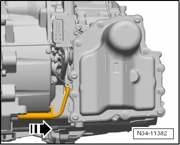
| Drain gear oil, then reinstall drain plug → Chapter. |
|
|
|


 Caution