volkswagen Workshop Repair Guides

Volkswagen Workshop Service and Repair Manuals

Installing > < Removing and installing engine
Removing
Removing
  Note
The engine is removed upwards without gearbox.
–  First check whether a coded radio is fitted. Obtain anti-theft coding beforehand if necessary.
–  With ignition switched off, disconnect earth strap from battery.
–  Detach or cut open cable tie.
–  Remove air filter → Chapter.
–  Remove battery and battery retainer.
   
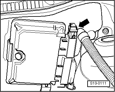
–  Release connector -1- from engine control unit and pull it off.
Vehicles with anti-theft secured engine control unit
–  Remove engine control unit → Chapter.
Continuation for all vehicles
–  Secure wiring harness to engine.
–  Open and close expansion tank cap to release pressure in cooling system.
  WARNING
Fuel supply lines are under pressure! Wear eye protection and gloves to avoid injuries and skin contact. Before loosening hose connections, wrap a cloth around the connection. Then release pressure by carefully pulling hose off connection.
  S10-0111
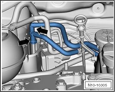
–  Pull off fuel supply and breather lines -arrows-.
–  Seal lines so that fuel system is not contaminated by dirt.
–  Observe rules for cleanliness → Chapter.
–  Remove Lambda probe and heat shield from exhaust manifold.
–  Remove selector mechanism from gearbox → 5-speed manual gearbox 02T; Rep. gr.34.
–  Drain coolant → Chapter.
–  Unbolt thermostat housing from cylinder head.
  Note
The coolant hoses remain connected to thermostat housing.
–  Remove poly V-belt → Chapter.
Vehicles with air conditioner
  Note
t  The air conditioning system lines must not be opened.
t  Prevent damage to condenser and refrigerant lines and hoses.
t  Do NOT stretch, kink or bend lines and hoses.
–  Remove air conditioner compressor → Heating, air conditioning system; Rep. gr.87.
–  Secure air conditioner compressor to lock carrier.
–  Ensure that lines are not kinked.
Continuation for all vehicles
–  Remove engine splash protection.
–  Remove front exhaust pipe → Chapter.
–  Unscrew electrical line from alternator.
  Caution
Bolt -1- must not be loosened.
  N10-10305
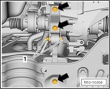
–  Remove pendulum support securing bolts -arrows-.
  N10-10308
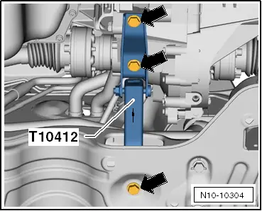
–  Install gearbox support -T10412-.
The -arrow- on gearbox support points forwards.
–  Tighten securing bolts -arrows- hand-tight.
  Note
t  The gearbox support -T10412- prevents lowering of the gearbox when the engine is removed and installed.
t  The pendulum support must be reinstalled once engine is reinstalled.
  N10-10304
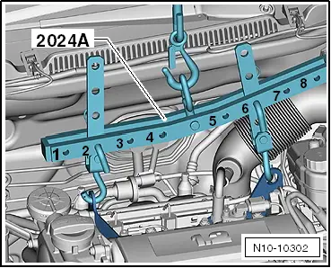
–  Attach lifting tackle -2024 A- as follows and lift slightly using workshop crane.
Belt pulley end: 1st hole in hook rail at position 2.
Flywheel end: 2nd hole in hook rail at position 6.
  Caution
Use securing pins on hooks and locking pins to avoid damage to engine and vehicle.
  Note
t  The positions marked 1…4 on the bar must be towards the belt pulley end.
t  The holes in the hook rails are counted up from the hook.
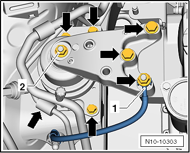
–  Unbolt earth wire -1-.
  Caution
Nut -2- must not be loosened.
  N10-10302
–  Unscrew securing bolts -arrows- for engine mounting.
–  Remove complete engine mounting.
–  Remove all gearbox flange securing bolts to engine.
–  Secure starter against falling.
–  Lift out assembly upwards. When doing this, turn assembly.
  Note
t  Bonnet must be raised slightly when lifting out assembly.
t  When lifted out, the assembly must be carefully guided to prevent damage to the bodywork.
Secure engine to engine and gearbox support -VAS 6095- to carry out repairs.
  N10-10303

Installing > < Removing and installing engine