
Polo Mk5
 Caution
| 1 - | Cylinder head with camshaft housing |
| q | Sealing surface must not be reworked. |
| q | With integrated camshaft bearings. |
| q | Removing and installing → Chapter. |
| q | Remove sealant residue. |
| q | Coat with D 154 103 A1 before fitting. |
| q | When installing, lower vertically from above so that dowel pins fit into holes in cylinder head. |
| 2 - | Cylinder block |
| q | 2 parts |
| q | Bolts must not be loosened. |
 Note
Note| The pistons must not be removed. |
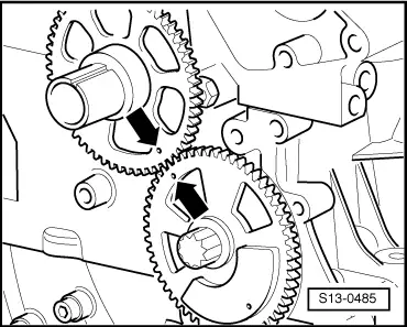
| 3 - | Balancer shaft |
| 4 - | Gear wheel |
| q | Must not be removed. |
| q | For balancer shaft. |
| q | Installation position of crankshaft sprocket relative to balancer shaft sprocket → Fig. |
| 5 - | Oil pump |
| q | Renew complete only. |
| 6 - | Guide pins |
| q | Specified torque: 20 Nm |
| 7 - | Guide rail |
| q | For timing chain → Item |
| 8 - | Chain sprocket |
| q | For crankshaft. |
| 9 - | Chain sprocket |
| q | For oil pump drive. |
| 10 - | Chain for oil pump |
| q | Before removing, mark direction of rotation (installation position). |
| 11 - | Chain sprocket |
| q | For oil pump. |
| q | Adjusting valve timing → Chapter. |
| 12 - | Oil sump |
| q | Remove and install on engines with liquid gasket → Chapter. |
| q | Clean sealing surface before fitting. |
| q | Install with silicone sealant D 176 404 A2. |
| 13 - | 9 Nm |
| 14 - | Cover |
| q | For chain sprocket for oil pump |
| 15 - | 20 Nm + turn 90° further |
| 16 - | O-ring |
Note| Always renew O-ring after removal. |
| 17 - | Bearing bush |
| 18 - | Seal |
| q | Removing and installing → Chapter. |
| 19 - | Belt pulley |
| q | Do not cant when installing. |
| q | Removing and installing poly V-belt → Chapter. |
| 20 - | 150 Nm + turn 180° further |
| q | Renew. |
| q | Oil before installing. |
| q | Lock with counterhold -3415-. |
| q | When tightening, lock crankshaft using locking pins -T10121-. |
| q | The turning further angle can be measured with a commercial protractor. |
| 21 - | 25 Nm |
| 22 - | 50 Nm |
| 23 - | 10 Nm |
| 24 - | To intake manifold. |
| 25 - | 10 Nm |
| 26 - | Oil separator |
| q | With vacuum valve. |
| 27 - | O-ring |
| q | Renew if damaged. |
| 28 - | Valve timing housing |
| q | Install with silicone sealant D 174 003 A2. |
| q | When fitting, install two -M6x75- studs into cylinder head and cylinder block as a guide. |
| q | To guide valve timing housing, secure oil sump in position with two bolts. |
| 29 - | Cover |
| 30 - | O-ring |
| q | Renew if damaged. |
| 31 - | 50 Nm + turn 90° further |
| 32 - | Tensioning plate |
| 33 - | Chain tensioner |
| 34 - | 9 Nm |
| 35 - | Timing chain |
| 36 - | Chain sprocket |
| q | For camshaft. |
|
|