E - Checking sender wheel installation position on crankshaft
E - Checking sender wheel installation position on crankshaft
E - Checking sender wheel installation position on crankshaft
–
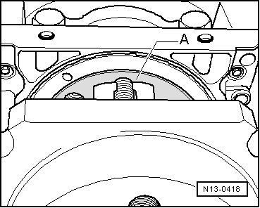
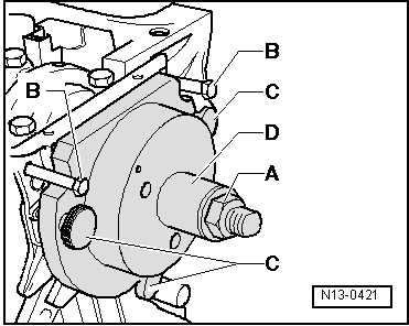
Screw hexagon nut -A- to end of threaded spindle.
–
Remove the two M6×35 mm bolts -B- from cylinder block.
–
Screw the three thumb wheels -C- out of sealing flange.
–
Remove assembly tool -T10017--D-.
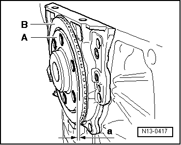
The sender wheel is in the correct installation position on the crankshaft if a gap -a- = 0.5 mm exists between crankshaft flange -A- and sender wheel -B-.
Note
To enable dimension -a- to be shown more clearly the crankshaft flange is illustrated without fitted assembly appliance -T10017-.
–
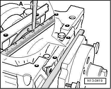
Place a vernier caliper against the crankshaft flange -A- (hatched area).
–
Measure the distance -a- between vernier caliper and sender wheel with a feeler gauge -A-.
 Note
Note