
Polo Mk5
|
|
|
|
|
|
|
|
|
|
|
|
|
|
|
|
|
|
|
|
|
|
|
|
|
|
|
|
|
 Note
Note
|
|
|
|
|
|
Note
|
|
|
|
|
|
Note
|
|
|
|
|
|
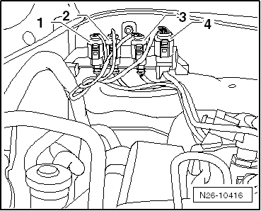
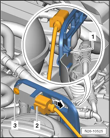
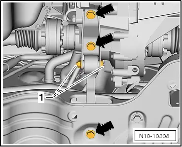
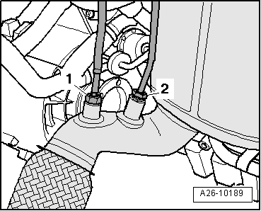
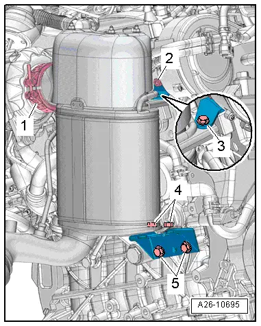
| 1. | position particulate filter on turbocharger and secure clip -1- loosely | |||
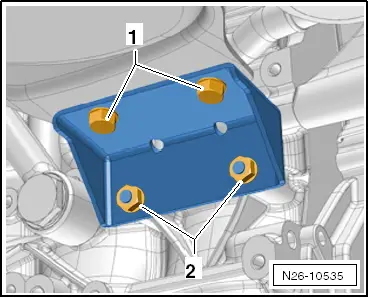
| 2. | screw bolts and nuts -2 … 5- in loosely by hand
| |||
| 3. | tighten clip -1- | |||
| 4. | tighten nuts and bolts -2- and -5- | |||
| 5. | tighten nuts and bolts -3- and -4- | |||
|
|