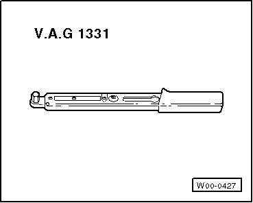
volkswagen Workshop Repair Guides

Volkswagen Workshop Service and Repair Manuals

Checking charge air system > < Removing and installing turbocharger
Removing and installing turbocharger (Polo)
Special tools and workshop equipment required
   
t  Tool set, 17 mm -T10395-
  W00-10767
t  Transport guard -T10403-
  W00-10761
t  Torque wrench -V.A.G 1331-
t  Used oil collection and extraction unit, e.g. -V.A.G 1782-
  Caution
When a mechanical fault is found on the turbocharger, e.g. a destroyed compressor impeller, it is not only sufficient to renew the turbocharger. To prevent this from causing further damage, perform the following repairs:
t  
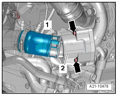
Check air filter housing, air filter element and intake hoses for soiling.
t  
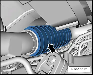
Check complete charged air routing and charge air cooler for foreign objects.
If foreign objects are found in the charge air system, the charged air routing must be cleaned and the charge air cooler must be renewed, if necessary.
→ Chapter „Safety precautions“
→ Chapter „Rules for cleanliness“
»Carry out the following work sequence«
Removing
–  With ignition switched off, disconnect earth strap from battery. → Electrical system; Rep. gr.27.
–  Remove engine cover panel → Chapter.
  W00-0427
–  Pull connector -1- off position sender for charge pressure positioner -G581- on turbocharger.
–  Remove air filter housing with air mass meter and suction hose → Chapter.
–  Remove plenum chamber bulkhead → General body repairs; Rep. gr.50.
Loosen particulate filter.
  N23-10377
–  To do this, unscrew bolt -1-.
–  Loosen bolt -2- and remove clamp.
  A26-11017
–  Disconnect electrical connector -3-.
–  Unscrew bolt -2-, remove pressure differential sender -G 505-, free hoses -1-.
  A26-11013
–  On decoupling element in front exhaust pipe, fasten the transport lock -T10403--arrow-.
  N26-10517
–  Unscrew bolts -1- and nuts -2-, remove bracket for particulate filter.
  N26-10535
–  Pull particulate filter from mountings -arrows-.
  A26-10956
–  Loosen securing bolts -arrows- of clamping sleeve, then push down backwards from front exhaust pipe.
–  Move particulate filter to side and fix using suitable means.
Right-hand drive vehicles → Chapter
Continuation for all vehicles
–  Remove oil supply line together with oil return line (turbocharger support) → Chapter.
–  Pull vacuum line -3- off turbocharger.
–  Remove pulsations damper with connecting hose to charge air pipe.
  V26-0733
–  Remove bolts -arrows-.
–  Take off pulsation damper -2-.
  A21-10478
–  Unscrew bolts -arrows- and remove heat shield.
  A21-10480
–  Unscrew nuts -arrows- and pull turbocharger with exhaust manifold off cylinder head.
  A21-10481
–  Carefully remove turbocharger from above in direction of gearbox.
Installing
  Caution
Before installing, check whether decoupling element of oil return line is bent and thus stretched. If this is the case, micro cracks can have formed and may cause leakage. If necessary, renew oil return line of turbocharger before installing.
–  Installation is carried out in the reverse sequence of removal. In the process, note the following:
t  Note installation position of exhaust temperature sender 1 -G 235-.
  N21-10518
Installation position of exhaust gas temperature sender with angled cable guide
  Note
When installing the exhaust temperature sender with angled cable guide, adhere to dimension -a- of 3 … 5 mm from the turbocharger support threaded connection.
Specified torques:
t  → Chapter „Assembly overview - turbocharger with attachments (Polo)“.
t  → Chapter „Assembly overview - components of oil supply line and turbocharger support to turbocharger “.
  N21-10161
–  Observe sequence when installing particulate filter:
  A26-10986
1.position particulate filter on turbocharger and secure clip -1- loosely
2.Screw in nuts -2, 4- and bolts -3, 5- loosely by hand
l  particulate filter and retainer must be able to move
3.tighten clip -1-
4.Tighten nuts -2, 4-
5.Tighten bolts -3, 5-


Checking charge air system > < Removing and installing turbocharger