
Polo Mk5
|
 Caution
| 1 - | Fuel return lines (from injectors) |
| q | To fuel tank. |
| q | The fuel return line must not be kinked, damaged or blocked. |
| q | The fuel return lines must not be dismantled. |
| q | Only renew O-ring if necessary |
| q | The pressure retention valve maintains a residual pressure in the return lines. |
| q | This residual pressure is required for the control function of the injectors. |
| q | Check pressure retention valve → Chapter. |
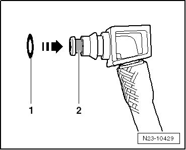
| 2 - | Fuel pressure regulating valve -N276- |
| q | Cannot be re-installed. |
| q | Removing and installing → Chapter. |
| q | 80 Nm |
| 3 - | Fuel return lines (from injectors) |
| 4 - | Bolt |
| q | 10 Nm |
| 5 - | High-pressure fuel pump |
| q | Removing and installing → Chapter. |
| q | With fuel metering valve -N290- (do not open). |
| q | After renewing, a first fuel filling must be performed (never allow the pump to run while it is still empty) → Chapter. |
| 6 - | Bolt |
| q | 20 Nm + turn 180° further. |
| 7 - | Hub |
| q | With sender ring |
| q | Use counterhold tool -T10051- to loosen and tighten. |
| q | To remove, use puller -T40064-. |
| 8 - | Nut |
| q | 95 Nm |
| 9 - | Toothed belt pulley on high-pressure pump |
| q | Bolts: 20 Nm + turn 90° further |
| 10 - | Bolt |
| q | 20 Nm + turn 45° further |
| 11 - | Bolt |
| q | 10 Nm |
| 12 - | High-pressure line |
| q | 28 Nm |
| q | Between high-pressure pump and rail element (high-pressure accumulator) |
| q | Install so that component is not under tension. |
 Note
Note| t | The high-pressure line may be re-used after the following checks: |
| t | Check taper seat of high-pressure line for deformation and cracks. |
| t | The line hole must not be deformed, constricted or damaged. |
| t | Corroded lines should no longer be used. |
| 13 - | Fuel pressure sender -G247- |
| q | Removing and installing → Chapter. |
| q | 100 Nm |
| 14 - | Rail element (high-pressure accumulator) |
| q | Removing and installing. |
| 15 - | Bolt |
| q | 22 Nm |
| 16 - | High-pressure lines |
| q | 28 Nm |
| q | Between rail element (high-pressure accumulator) and injectors |
| q | Do not interchange. |
| q | Install so that component is not under tension. |
Note| t | Observe cylinder specific markings when reusing high-pressure lines. |
| t | The high-pressure lines may be re-used after the following checks: |
| t | Check taper seat of respective high-pressure line for deformation and cracks. |
| t | The line hole must not be deformed, constricted or damaged. |
| t | Corroded lines should no longer be used. |
| 17 - | Gasket |
| q | Renew cylinder head cover if damaged. |
| 18 - | Gasket |
| 19 - | Injectors |
| q | Removing and installing → Chapter. |
| q | The following components and seals/O-rings must be renewed each time on removal/installation: „copper seal“, „O-ring for injector bore“, „bolt for clamping piece“ and „retaining clip for return connection“. |
| q | The following components and seals/O-rings must be renewed when an injector is renewed: „clamping piece“, „copper seal“, „bolt for clamping piece“ |
| q | Before re-using „high-pressure line“, perform visual check of taper seats for damage such as transverse scores or corrosion; always renew if damaged. |
| q | If they are to be re-installed, injectors, high-pressure fuel lines and clamping pieces must always be re-fitted in their original positions (i.e. on the same cylinder). |
| 20 - | Bolt for clamp |
| q | Renew. |
| Tighten securing bolts to a maximum of 1 to 2 Nm at first. |
| After the high-pressure lines have been fitted. Final tightening torque: 8 Nm + turn 180° further. |
| 21 - | O-ring (leakage lines, fuel return lines) |
| q | Following component must be renewed every time the fuel return lines are removed and installed: „fuel return line retaining clip“ |
| q | Only renew O-ring if necessary |
Note
|
|
|

| 1 - | Fuel return line for 0.5 bar low-pressure fuel system → Item |
| q | Flexible. |
| q | With pressure retention valve |
| 2 - | Fuel return line for 6.0 bar low-pressure fuel system → Item |
| q | Flexible. |
| q | With pressure retention valve |
| 3 - | Fuel return lines for 0.5 bar low-pressure fuel system |
| q | Rigid. |
| 4 - | Fuel return lines for 6.0 bar low-pressure fuel system |
| q | Rigid. |
|
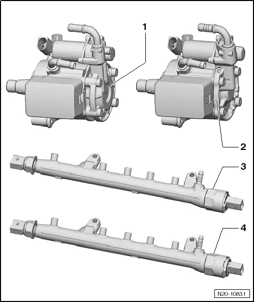
| 1 - | High-pressure pump for 0.5 bar low-pressure fuel system |
| q | With booster pump fitted to high-pressure pump. |
| 2 - | High-pressure pump for 6.0 bar low-pressure fuel system |
| q | Without booster pump. |
| q | The requisite 6.0 bar pressure in the low-pressure fuel system is generated by the fuel delivery unit. |
| 3 - | Fuel pressure regulating valve -N276- 0.5 bar low-pressure fuel system |
Note| t | Fuel pressure regulating valve -N276- of 0.5 bar low-pressure fuel system looks similar to that of 6.0 bar low-pressure fuel system. |
| t | Observe the index as per → ETKA (electronic parts catalogue). |
| q | -High-pressure accumulator- with fuel pressure sender -G247- |
| 4 - | Fuel pressure regulating valve -N276- 6.0 bar low-pressure fuel system |
Note| t | Fuel pressure regulating valve -N276- of 6.0 bar low-pressure fuel system looks similar to that of 0.5 bar low-pressure fuel system. |
| t | Observe the index as per → ETKA (electronic parts catalogue). |
| q | -High-pressure accumulator- with fuel pressure sender -G247- |