
Polo Mk5
| Assembly overview - timing chain |
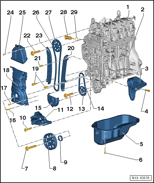
| 1 - | Cylinder head with cylinder head cover |
| q | Remove and install cylinder head → Chapter. |
| q | Remove and install cylinder head cover → Chapter. |
| q | Sealing surface must not be reworked. |
| q | With integrated camshaft bearings. |
| q | Remove sealant residue. |
 Caution
|
| q | Apply sealant D 189 500 A1 and D 154 103 A1 before positioning. |
| q | When installing, insert vertically from above so that dowel pins fit into holes in cylinder head |
| 2 - | Cylinder block |
Caution
|
| q | Dismantle and assemble cylinder block → Chapter. |
| q | Dismantle and assemble pistons and conrods → Chapter |
| 3 - | Bottom ancillary bracket |
| q | For tensioning element and air conditioner compressor. |
| q | Remove and install → Chapter |
| q | Remove and install top ancillary bracket → Chapter |
| 4 - | 25 Nm |
| 5 - | Oil sump |
| q | Remove and install → Chapter |
| q | Clean sealing surface before fitting. |
| q | Install with silicone sealant D 176 600 A1. |
| 6 - | 13 Nm |
| 7 - | 150 Nm + turn 180° further. |
| q | Remove and install crankshaft pulley → Chapter. |
| q | Renew. |
| q | Contact surface for securing bolt must be free of oil and grease. |
| q | Oil threads before inserting. |
| q | Secure belt pulley against turning with counterhold tool -3415-. |
| q | The turning further angle can be measured with a commercial protractor. |
| 8 - | Belt pulley |
| q | With diamond coated washer (clipped onto belt pulley) |
| q | Observe tightening procedure → Chapter. |
| q | Contact surfaces must be free of oil and grease. |
| q | Secure belt pulley against turning with counterhold tool -3415-. |
| q | Remove and install poly V-belt → Chapter. |
| 9 - | Seal |
| q | Renew. |
| q | Remove and install → Chapter |
| 10 - | 50 Nm |
| 11 - | Engine support |
| q | For assembly mounting |
| 12 - | 20 Nm + turn 90° further |
| q | Renew. |
| 13 - | Chain sprocket |
| q | For oil pump drive. |
| q | Contact surfaces must be free of oil and grease. |
| q | Lock sprocket using counterhold -T10172-. |
| 14 - | Oil pump drive chain |
| q | Before removing, mark direction of rotation (installation position). |
| 15 - | Cover |
| 16 - | 5 Nm + turn 30° further |
| q | Bolt: M6x40 |
| q | Tighten with torque wrench -VAS 6583-. |
| 17 - | 5 Nm + turn 30° further |
| q | Bolt: M6x20 |
| q | Tighten with torque wrench -VAS 6583-. |
| 18 - | Bottom valve timing housing |
| q | Remove and install → Chapter |
| q | Install with sealant D 176 501 A1 |
| 19 - | Bearing mounting |
| q | Specified torque. 18 Nm |
| 20 - | Guide rail |
| q | For timing chain. |
| 21 - | Bearing mounting |
| q | Specified torque. 18 Nm |
| 22 - | 50 Nm + turn 90° further |
| q | Renew. |
| 23 - | Tensioning plate |
| q | For timing chain. |
| 24 - | 8 Nm |
Caution
|
| 25 - | Top valve timing housing |
| q | Install with sealant D 176 501 A1 |
Caution
|
| 26 - | Timing chain |
 Note
Note| t | Only in vehicles manufactured from June 2011: |
| t | If timing chain has been removed and installed or renewed, erase learnt values and adapt engine control unit → Vehicle diagnostic tester„Guided Functions“. |
| q | Remove and install → Chapter |
| 27 - | Chain sprocket |
| q | Lock sprocket using counterhold -T10172-. |
| 28 - | Chain tensioner |
| q | For timing chain. |
| q | Specified torque: 60 Nm |
| 29 - | Seal |
| q | Renew. |