volkswagen Workshop Repair Guides

Volkswagen Workshop Service and Repair Manuals

High-pressure pump > < Removing and installing injectors
Renewing seals on injectors
Special tools and workshop equipment required
   
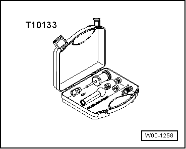
t  Tool set -T10133-
Procedure
Renewing Teflon seal
–  Remove injectors → Chapter.
–  Clean injector carefully.
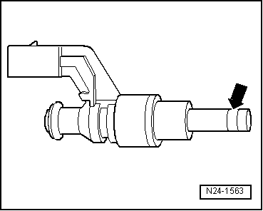
–  Carefully cut open seal with a knife as shown -arrow-. Avoid contact between knife blade and valve body under all circumstances.
  W00-1258
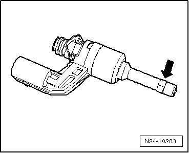
–  Remove old seal and clean seal groove in area of seal -arrow-. Remove coking deposits using a brass wire brush.
  N24-10283
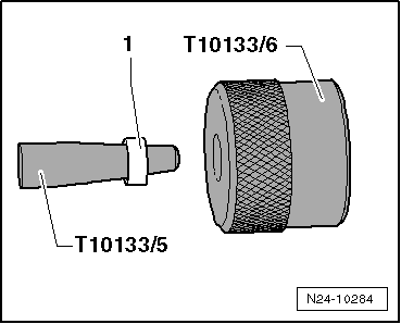
–  Fit new oil seal -1- onto assembly cone -T10133/5-. Using assembly sleeve -T10133/6- (knurling points to seal -1-), gently slide seal onto assembly cone -T10133/5- as far as possible.
–  Turn retaining frame -T10133/6- upside down.
The knurling no longer faces towards the seal.
  N24-10284
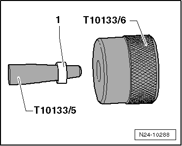
–  Push oil seal -1- onto end of assembly cone -T10133/5-.
–  Now place assembly cone -T10133/5- with seal onto injector from front. Slide seal further onto injector using assembly sleeve -T10133/6-.
  N24-10288
The seal is not yet seated in its groove.
–  Remove assembly sleeve -T10133/6- and assembly cone -T10133/5-.
–  Slide seal into annular groove by hand.
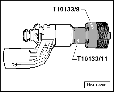
–  Position spacer sleeve -T10133/11- onto valve body.
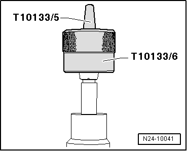
–  Now push calibration sleeve -T10133/7- over seal to stop onto spacer sleeve -T10133/11-.
  N24-10041
–  Pull off calibration sleeve -T10133/7- again.
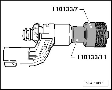
–  Now push calibration sleeve -T10133/8- over seal to stop onto spacer sleeve -T10133/11-.
–  Pull off calibration sleeve -T10133/8- again.
  N24-10285
Now the Teflon seal has correct installation dimensions.
Renewing support washer
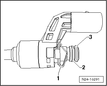
–  Remove O-ring -3-.
–  Cut support washer -2- open with a small pair of side cutters and remove it.
  N24-10286
–  Pull spring element -1- off injector and replace with retaining plate -T10133/12-.
–  Slide support washer -1- into first groove -arrow- on injector using calibration sleeve -T10133/17- (knurled side faces towards injector).
  N24-10291
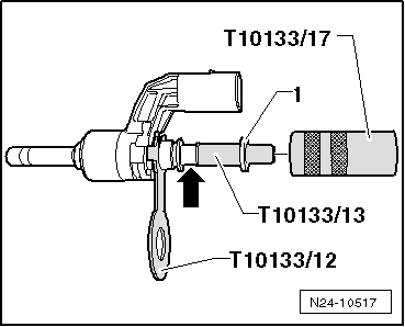
–  Place new support washer -1- onto assembly cone -T10133/13- and position onto injector as shown.
–  Now turn calibration sleeve -T10133/17- over.
Knurled side is now no longer pointing towards injector.
  N24-10517
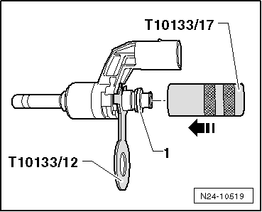
–  Slide calibration sleeve -1- in -direction of arrow- to stop on retaining plate -T10133/12-.
–  Pull calibration sleeve -T10133/17- down again.
The support washer now has correct installation dimensions.
  N24-10519
–  Now position a new spring element -1- for retaining plate -T10133/12- and position a new O-ring -3- in front of support washer -2-.
  Note
  N24-10291
The Teflon seal -arrow- must not be oiled to install injector.
–  Install injectors → Chapter.
Further installation is carried out in the reverse sequence of removal.
  N24-1563

High-pressure pump > < Removing and installing injectors