volkswagen Workshop Repair Guides

Volkswagen Workshop Service and Repair Manuals

Installing engine (Polo) > < Removing and installing engine
Removing engine (Polo)
  Note
The engine is removed downwards together with the gearbox.
   
Special tools and workshop equipment required
t  Engine support -T10416- with adapters /1, /2, /3
t  Torque wrench -V.A.G 1331-
t  Engine and gearbox jack -V.A.G 1383 A-
t  Engine and gearbox support -VAS 6095-
t  Drip tray for workshop hoist -VAS 6208-

   
t  Hose clip pliers -VAS 6340-
t  Stepladder -VAS 5085-
t  Torque wrench (40 … 200 Nm) -V.A.G. 1332-

  Note
Before carrying out further work, disconnect battery earth strap. Check whether a coded radio is fitted. Obtain anti-theft coding first if necessary.
   
–  Lift engine cover panel at points -1- and pull it forwards in direction of -arrow-.
  N10-10281
–  Unbolt heat shield over turbocharger -arrows-.
–  Pull hose -1- off at camshaft housing.
  N21-10220
–  Open spring-type clip -2- and pull intake hose off.
–  Pull intake hose out of intake connection.
–  Unscrew securing bolt and pull air filter housing -4- upwards.
–  Disconnect battery → Electrical system; Rep. gr.27.
–  Remove battery and battery holder → Electrical system; Rep. gr.27.
  N10-10514
–  Remove noise insulation securing bolts -arrows-.
–  Remove front left and right wheel housing liners → General body repairs; Rep. gr.66.
–  Open and close expansion tank cap to release pressure in cooling system.
–  Drain coolant → Chapter.
–  Observe rules for cleanliness → Chapter.
  WARNING
Fuel supply lines are under pressure! Wear eye protection and gloves to avoid injuries and skin contact. Before loosening hose connections, wrap a cloth around the connection. Then release pressure by carefully pulling hose off connection.
  N10-10358
–  Separate fuel supply line -1- and line to activated charcoal filter -2-. Press release tabs to do this.
–  Pull coolant hoses off at heat exchanger behind intake manifold.
–  Pull off connector -1-.
  N10-10317
–  Pull vacuum hose -2- off at vacuum pump for brakes -V192--3-.
Right-hand drive vehicles only
–  Additionally pull vacuum hose off at brake servo.
Continuation for all vehicles
–  Secure vacuum hose to engine with cable tie.
–  Pull off connector -1-.
  N10-10521
–  Pull coolant hoses -2- off coolant reservoir.
–  Unscrew securing bolts -3- and pull coolant reservoir upwards.
  N10-10518
–  Release coolant hoses -arrows- at gearbox side and pull them off.
–  Pull coolant hoses off at radiator and remove completely.
–  Remove engine control unit → Chapter.
–  Remove wiring harness from line guides and secure to engine with cable ties.
–  Remove main fuse box in engine compartment → Electrical system; Rep. gr.97.
–  Secure main fuse box to side of body with cable ties.
–  Remove selector lever cable → Rep. gr.34.
  N10-10321
–  Unscrew securing nuts on turbocharger -arrows-.
  N10-10520
–  Remove charge air hose -arrow-.
–  Remove air conditioner compressor → Heating, air conditioning; Rep. gr.87
  Note
The air conditioning system lines must not be opened.
–  Secure air conditioner compressor to lock carrier.
–  Ensure that lines are not kinked.
–  Disconnect connector -3- for Lambda probe after catalytic converter -G130-.
  N10-10519
–  Also disconnect all further connectors at gearbox support.
–  Unscrew securing bolts -1- for charge air pipe.
–  Unscrew securing bolts -4- and remove bracket -5-.
–  Pull upper charge air hose off turbocharger.
–  Remove charge air pipe downwards.
–  Press front exhaust pipe mountings from pins.
  N10-10516
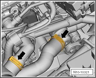
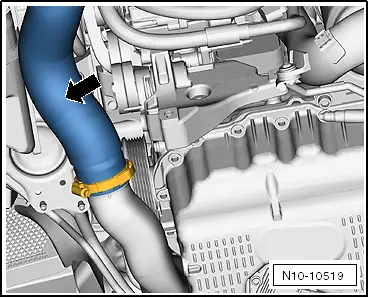
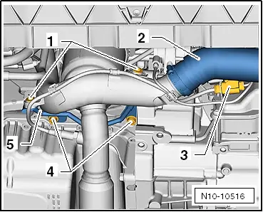
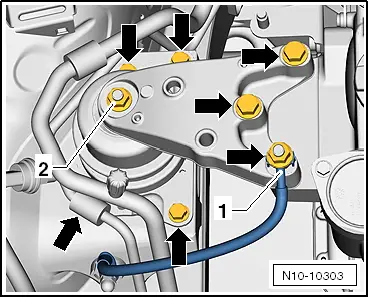
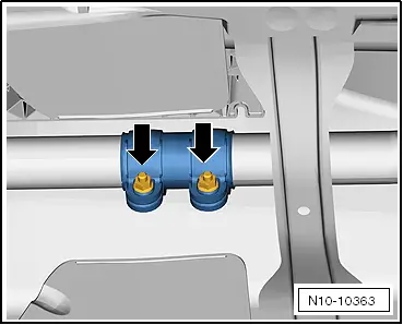
–  Loosen securing bolts of clamp -arrows- and slide to rear.
–  Remove catalytic converter with front exhaust pipe downwards.
–  Remove poly V-belt → Chapter.
–  All cable ties that are opened or cut through when the engine is removed must be renewed/replaced in the same position when the engine is installed.
–  Disconnect all electrical wiring from gearbox, alternator and starter and lay to side.
–  Pull off or disconnect all other electrical connections as necessary from engine and lay to side.
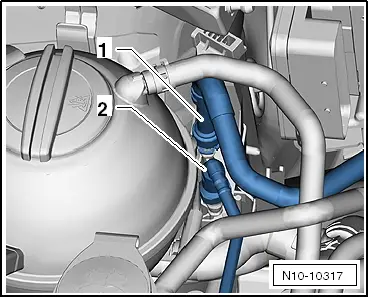
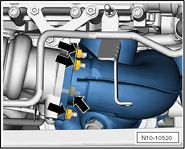
–  Pull vacuum and breather hoses off engine.
–  Pull connectors off thermal switch and radiator fan.
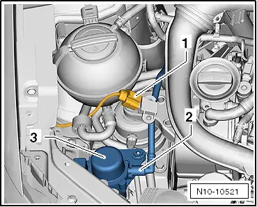
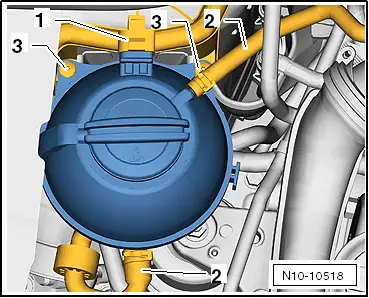
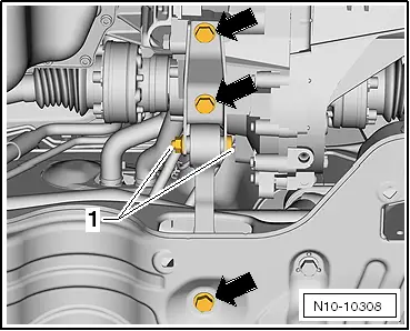
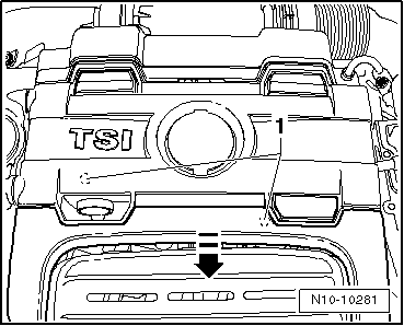
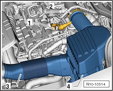
–  Remove right and left drive shafts → Running gear, axles, steering; Rep. gr.40.
  Caution
Bolt -1- must not be loosened.
  N10-10363
–  Remove pendulum support securing bolts -arrows-.
–  Remove subframe → Running gear, axles, steering; Rep. gr.40.
  N10-10308
Engine support -T10416- with adapters -/1-, -/2- and -/3- is required to lower engine with gearbox.
  N10-10328
–  Screw adapter -T10416/1- to stop into crankcase.
–  Position the engine support -T10416- with adapters -/2- and -/3- on crankcase.
–  Secure engine support -T10416- hand-tight to crankcase using a bolt -1-.
  N10-10329
–  Tighten all bolts on engine support -T10416- to 20 Nm.
  Note
Adjuster nut -2- sets correct angle between pin on engine support -T10416- and engine and gearbox jack -V.A.G 1383 A-.
–  Position engine and gearbox jack -V.A.G 1383 A- on engine support -T10416-.
–  Lift engine and gearbox lightly using engine and gearbox jack -V.A.G 1383 A-.
  Note
To remove securing bolts use a stepladder -VAS 5085-.
–  Unbolt earth wire -1-.
  Caution
Nut -2- must not be loosened.
  N10-10330
–  Unscrew securing bolts -arrows- for engine mounting.
–  Remove complete engine mounting.
  N10-10303
–  Unscrew securing bolts -arrows- at gearbox mounting.
  Note
When lowering engine, guide it carefully to prevent damage.
–  Carefully lower engine and gearbox.
Secure engine to engine and gearbox support -VAS 6095- to carry out repairs.
–  Unbolt gearbox.
–  Secure engine on engine and gearbox support -VAS 6095-.
  N10-10517

Installing engine (Polo) > < Removing and installing engine