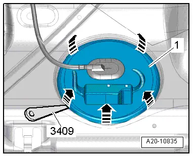
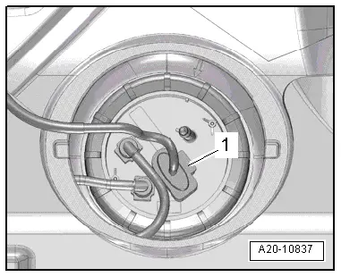
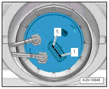
| Fuel gauge sender -G- installed: |
| –
| Connect multimeter between contacts -2- and -3- in order to measure resistance. |
| l
| Sender at lower stop: 266 … 274 Ω. |
| l
| Sender at upper stop: 67 … 73 Ω. |
| –
| Connect multimeter between contacts -2- and -4- in order to measure resistance. |
| l
| Sender at lower stop: 67 … 73 Ω. |
| l
| Sender at upper stop: 266 … 274 Ω. |
| –
| Connect multimeter between contacts -3- and -4- in order to measure resistance. |
| l
| Any sender position: 335 … 345 Ω. |

Note | t
| If the resistance is 0 Ω, there is a short circuit. If the resistance is ∞ Ω, there is an open circuit in the wiring. |
| t
| To test the maximum and minimum resistance values for „fuel tank full“ and „fuel tank empty“, remove the fuel delivery unit and move the sender float all the way to its top or bottom position. |
| t
| The following values are obtained with the fuel delivery unit removed, due to the greater travel of the float arm: |
| Fuel gauge sender -G- removed: |
| –
| Connect multimeter between contacts -2- and -3- in order to measure resistance. |
| l
| Sender at lower stop: 285 … 295 Ω. |
| l
| Sender at upper stop: 48 … 52 Ω. |
| –
| Connect multimeter between contacts -2- and -4- in order to measure resistance. |
| l
| Sender at lower stop: 48 … 52 Ω. |
| l
| Sender at upper stop: 285 … 295 Ω. |
| –
| Connect multimeter between contacts -3- and -4- in order to measure resistance. |
| l
| Any sender position: 335 … 345 Ω. |
| –
| If a large deviation in values is recorded or if a measured value of 0 Ω (short circuit) or of ∞ Ω (open circuit) is recorded and if no faults have been detected in the electrical wiring and cables, renew fuel gauge sender -G-. |
| –
| Remove and install fuel gauge sender -G- → Chapter. |
|
|
|