volkswagen Workshop Repair Guides

Volkswagen Workshop Service and Repair Manuals

Removing and installing power steering sensor G250 , right-hand drive vehicle > < Assembly overview for electro-hydraulic power steering, right-hand drive vehicle
Removing and installing power steering box, right-hand drive vehicle
   
Removing and installing power steering box, right-hand drive vehicle
Special tools and workshop equipment required
t  Ball joint puller -3287 A-
t  Torque wrench -V.A.G 1331-
t  Flared ring spanner tool insert AF 17 -V.A.G 1331/10-
t  Torque wrench -V.A.G 1332-
t  Engine and gearbox jack -V.A.G 1383 A- with universal gearbox support -V.A.G 1359/2-
t  Drip tray for workshop hoist -VAS 6208-

Removing
–  Disconnect earth strap of battery with ignition switched off → Electrical system; Rep. Gr.27.
Vehicles with air filter on left in engine compartment
–  Remove battery and battery tray → Electrical system; Rep. Gr.27.
Continuation for all vehicles
–  Lift vehicle far enough to take weight off front axle.
–  Remove front wheels.
   
–  Remove nuts -arrows-.
–  Pull swivel joint out of suspension link.
  N40-10350
–  Unscrew cap -1- from motor/pump unit -2-.
–  Draw off as much hydraulic fluid as possible from motor/pump unit using a suction bottle.
  N48-0602
–  Unscrew bolt -arrow- from universal joint -1- and pull off universal joint in -direction of arrow-.
–  Remove front wheels.
  N48-10418
–  Loosen nut -1- on track rod end -2- but do not remove completely.
Leave nut screwed on a few turns to protect thread on pin.
–  Press track rod ball joint -2- off steering arm.
  N48-10401
–  Unscrew hexagon nut -1- from coupling rod (left and right sides).
–  Pull out coupling rod -3- from anti-roll bar -2- on left and right side.
  N40-10382
–  Pull connector -1- off power steering sensor -G250-.
  N48-10420
–  Unscrew banjo bolt -1- (19 mm) for pressure line from steering box.
–  Close off line with a plastic bag and adhesive tape.
  N48-10421
–  Unscrew retaining screw -1- (17 mm) for return hose from steering box.
–  Close off line with a plastic bag and adhesive tape.
–  Seal power steering box threaded holes with plastic sealing plugs.
  N48-10422
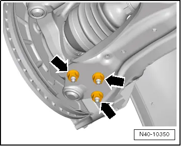
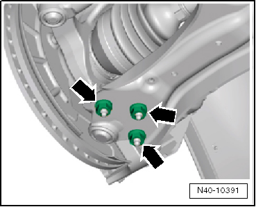
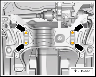
–  Remove steering box bolts -arrows- from subframe.
–  Fix position of subframe → Chapter.
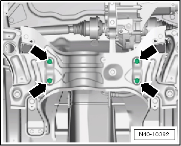
–  Lower subframe using engine and gearbox jack -V.A.G 1383 A-.
–  Remove power steering box to rear.
Installing
t  
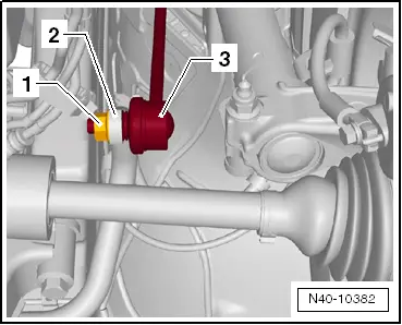
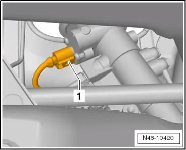
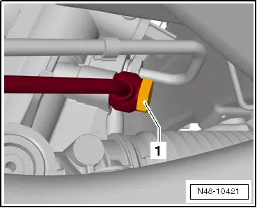
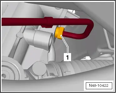
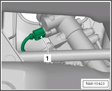
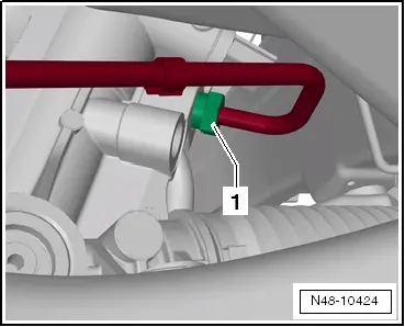
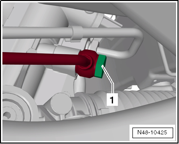
Use new sealing rings for hose/line connections.
t  Coat seal on steering box with suitable lubricant, e.g. soft soap, before installing steering box.
t  
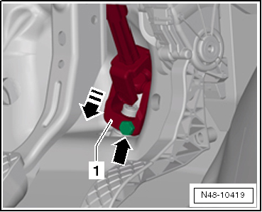
After fitting the steering box to the drive shaft ensure that the seal is not kinked against the assembly plate on the steering box. The opening to the footwell must seal correctly. Otherwise, this can result in water leaks and/or noise.
t  Ensure sealing surfaces are clean.
t  When renewing the power steering box also install new bellows on the track rods.
Before inserting bolts for subframe, position power steering box on subframe and insert power steering box bolts.
–  Secure subframe → Chapter.
  N40-10330
–  Bolt swivel joint to suspension link with new nuts -arrows-.
Ensure that bellows are not damaged or twisted.
  N40-10391
–  Bolt steering box to subframe -arrows-.
–  Bolt track rod to steering arm.
  N40-10392
–  Connect connector -1- to power steering sensor -G250-.
  N48-10423
–  Screw union bolt -1- (17 mm) for return hose onto steering box.
  N48-10424
–  Screw banjo bolt -1- (19 mm) for pressure line onto steering box and tighten.
Make sure that pressure line does not make contact with body or subframe.
–  Fill up with fresh hydraulic fluid - use a hose (approx. 400 … 500 mm long) and a funnel to do this.
–  Use hydraulic fluid -G 004 000 M2-.
Vehicles with air filter on left in engine compartment
–  Install battery and battery holder → Electrical system; Rep. Gr.27.
Continuation for all vehicles
  N48-10425
–  Position universal joint -1- onto steering pinion.
–  Insert new hexagon bolt -arrow- and tighten.
–  Connect earth strap of battery → Electrical system; Rep. Gr.27.
–  Install wheels and tighten bolts or nuts → Chapter.
–  Bleed steering system → Chapter.
–  Check hydraulic fluid level → Chapter.
After installation, check position of steering wheel during road test.
If steering wheel is not in straight-ahead position or if a new steering box was installed, front axle track must be checked and if necessary adjusted!
–  Check toe adjustment → Chapter.
  N48-10419
Specified torques
ComponentSpecified torque
Swivel joint to suspension link
t  Use new bolts.
100 Nm
Steering box to subframe
t  Use new bolts.
50 Nm + 90°
Track rod to steering arm20 Nm + 90°
Power steering sensor -G250- in steering box6 Nm
Union screw for return line to steering box
t  Use new oil seals.
30 Nm
Banjo bolt for pressure line to steering box
t  Use new oil seals.
40 Nm
Universal joint to steering box
t  Use new bolt
30 Nm


Removing and installing power steering sensor G250 , right-hand drive vehicle > < Assembly overview for electro-hydraulic power steering, right-hand drive vehicle