| t
| Repairs must not be performed on the motor/pump unit |
| t
| If problems are reported, determine the cause by means of a function test, pressure test, leakage test and self-diagnosis. |
| t
| If a fault is found, the motor/pump unit must be renewed. |
| t
| Residual quantities of hydraulic fluid remain in the motor/pump unit and in the return and pressure lines after extracting. |
| t
| Do not re-use hydraulic fluid which has been drained off. |
| t
| Pressure and return lines must not be clamped off with hose clamps, e.g. -3094-, or other tools. Clamping can cause damage to the pressure line or return line. |
| t
| When bending or repositioning the pressure line or return line, make sure that the bending radius is not less than 100 mm to prevent damaging the lines. |
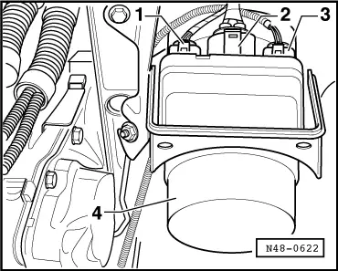
| Vehicles with air filter on left in engine compartment |
| Continuation for all vehicles |
|
|
|