volkswagen Workshop Repair Guides

Volkswagen Workshop Service and Repair Manuals

Assembly overview - steering column, right-hand drive vehicle > < Assembly overview - steering column, left-hand drive
Removing and installing steering column, left-hand drive vehicle
Special tools and workshop equipment required
   
t  Torque wrench -V.A.G 1331-
  W00-0427
t  Torque wrench -V.A.G 1332-
Removing
Only the complete steering column is supplied as a replacement part. Repair is not possible.
Steering lock housing can be converted → Electrical system; Rep. Gr.94.
  WARNING
The following conditions must be met before starting work on the electrical system and removing the steering wheel:
t  Unbolt earth strap from battery → Rep. Gr.27.
t  Wheels must be in straight-ahead position.
Failure to comply with these precautions may lead to subsequent failure of the airbag system!
–  Turn wheels to straight-ahead position.
–  Pull down lever on side of steering column.
–  Swing steering column down as far as possible and pull out.
–  Press lever on side of steering column back up.
–  Remove airbag → General body repairs, interior; Rep. Gr.69.
–  Remove steering wheel → Chapter.
–  Remove steering column switch → Electrical system; Rep. Gr.94.
Removal and installation of the coil connector with slip ring must be carried out with the wheels in the straight-ahead position.
Coil connector with slip ring is secured as a new part in the centre position with a cable tie.
Vehicles with ESP
Vehicles with ESP are additionally equipped with a steering angle sensor -G85-. It is fitted in a housing together with the slip ring and coil connector.
After installation work on steering column switch, basic settings for steering angle sender -G85- must be carried out.
Continuation for all vehicles
  W00-0428
–  Unplug connector -1- from immobiliser reader coil -D2-.
On vehicles with an automatic gearbox, the ignition key removal lock cable must be also be unhooked → Rep. Gr.37.
–  Pull connector -2- off steering lock housing.
–  Unbolt earth cable for steering column.
–  Remove earth cable and steering column switch line from cable retainer.
–  Fold floor covering back slightly.
  N48-10392
–  Unscrew bolt -arrow- from universal joint -1- and pull off universal joint in -direction of arrow-.
  N48-10393
–  Unscrew securing bolt -arrow- on left of brake pedal from mounting bracket.
  N48-10394
–  Unscrew bolts -arrows- from steering column and hold steering column.
  N48-10397
–  Lower steering column -1- slightly and carefully pull forwards out of guide -arrow- on mounting bracket -2-.
  Caution
Take great care to ensure the steering column is handled and transported correctly → Chapter.
Installing
  N48-10396
–  Insert steering column -1- with raised areas -arrow A- into guides -arrow B- on mounting bracket -2-.
  N48-10427
–  Swivel steering column up, align with mounting bracket and position.
Holes -arrows- and journals -1- must align.
The correct installation position of the steering column relative to the mounting bracket is guaranteed only in this way.
  Note
When installing steering column, adhere strictly to bolting sequence.
  N48-10395
–  Tighten steering column bolts -arrows-.
–  Release lever on side of steering column.
  N48-10408
–  Screw in lower securing bolt -arrow- and tighten.
  N48-10409
–  Position universal joint -1- onto steering pinion.
–  Insert new hexagon bolt -arrow- and tighten.
  N48-10410
–  Fit wiring connectors -1- on steering lock housing.
–  Connect plug -2- of immobiliser reader coil -D2-.
–  Insert earth cable and steering column switch line into cable retainer.
–  Tighten earth cable for steering column.
–  Insert cable in cable retainer and close at tabs.
The ignition key removal lock cable also needs to be hooked in on vehicles with an automatic gearbox → Rep. Gr.37.
–  Install steering column switch → Electrical system; Rep. Gr.94.
Vehicles with ESP
–  Install steering angle sender -G85- → Electrical system; Rep. Gr.94.
Continuation for all vehicles
–  Install steering column trim → General body repairs, interior; Rep. Gr.70.
–  Install steering wheel → Chapter.
–  Install airbag module → General body repairs, interior; Rep. Gr.69.
  WARNING
When connecting battery ensure that no people are in the vehicle!
Vehicles with ESP
–  Perform basic setting for steering angle sender -G85- using vehicle diagnosis, testing and information system -VAS 5051 A-.
  N48-10411
Specified torques
ComponentSpecified torque
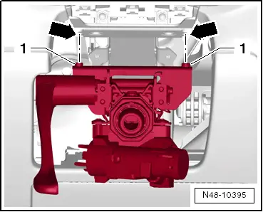
Steering column to upper mounting bracket20 Nm
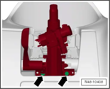
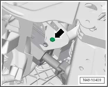
Steering column to lower mounting bracket8 Nm
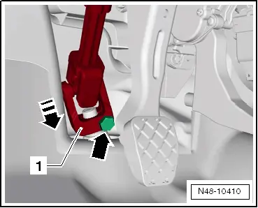
Steering column to steering box
t  Use new bolt
30 Nm


Assembly overview - steering column, right-hand drive vehicle > < Assembly overview - steering column, left-hand drive