
Quantum Syncro AWD L5-2226cc 2.22L SOHC (1987)
Fuel Pump Relay: Description and Operation
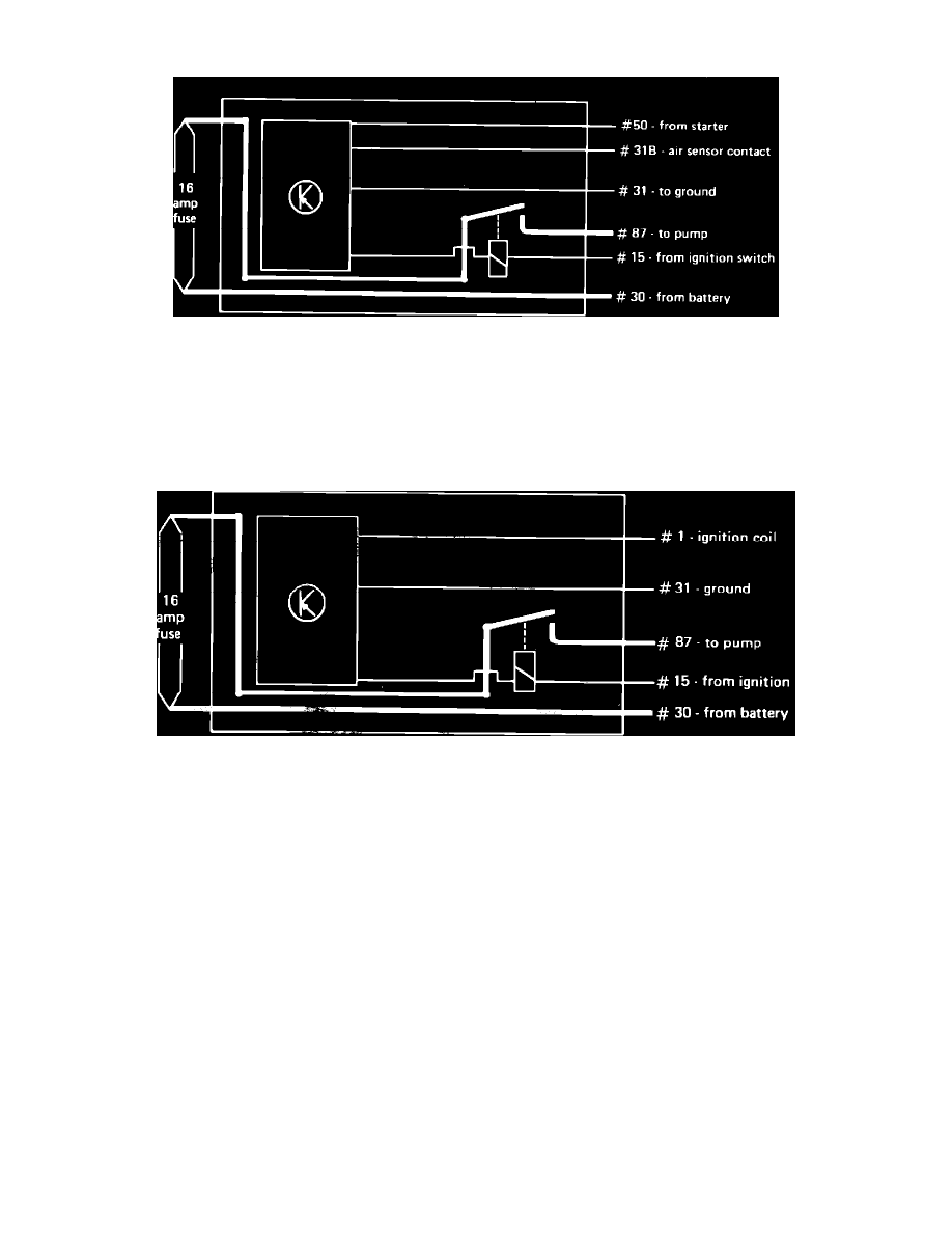
Fig. 16 Relay diagram. Six Pin Relay
Six Pin relay
With ignition on, current is supplied to the pull-in coil which is grounded through the transistorized circuit whenever the starter is operating (50) or the
air sensor contact (31B) is open during normal running. The pull-in coil completes the circuit between battery terminal 30 and the fuel pump via the 16
amp fuse on top of the pump relay, Fig. 16. To run pump with engine off for testing purposes, remove air flow sensor electrical connector with ignition
on.
Fig. 17 Relay diagram. Five Pin Relay
Five Pin Relay
With ignition on, current is supplied to the pull-in coil which is grounded through the transistorized circuit whenever impulses are received from the
ignition coil during starting or normal running, Fig. 17. To run pump with engine off for testing purposes, remove relay and bridge relay board terminals
L13 and L14 with a jumper wire with an in-line switch, (US 4480 or equivalent).