
Rabbit Convertible L4-1715cc 1.7L SOHC (1982)
Air Flow Meter/Sensor: Testing and Inspection
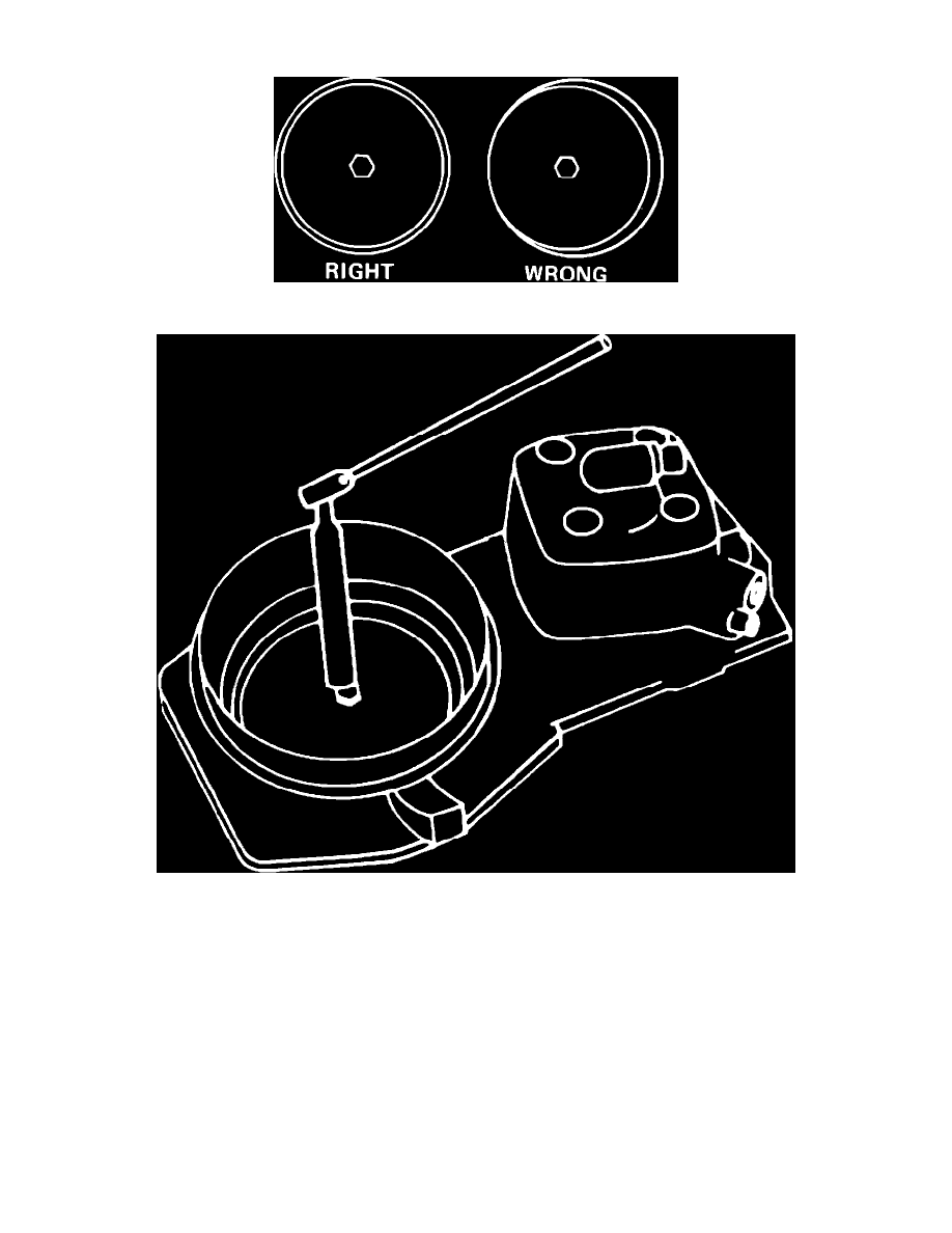
Fig. 25 Sensor plate adjustment
Fig. 26 Free movement check
1.
Start engine and run briefly then shut off engine and remove air flow sensor boot.
2.
Ensure that sensor plate is centered in air cone, Fig. 25. Center plate by using at least three 0.1 mm (.004 in) feeler gauges placed evenly around
perimeter of sensor plate gap with bolt slightly loosened, then tighten bolt.
3.
Lift sensor plate with magnet or pliers, Fig. 26, and check for even resistance over entire travel of sensor plate.
4.
If resistance is uneven, remove fuel distributor and inspect plunger for contamination.
NOTE: The piston and its sleeve, in the fuel metering distributor, are machined to a tolerance of .00025", and are a matched set. When handling
these parts it is advisable to avoid any impact or damage as the parts are not independently replaceable.
a. Remove the plunger.
b. Check for gum deposits and signs of seizing. If gum deposits are found on the piston clean it with clean gasoline.
c. Ensure that the piston does not bind inside its sleeve by sliding it back and forth while turning it.
d. If a high spot is found, replace the metering distributor.
e. Install a new "O" ring between fuel distributor and air flow sensor housing.
f.
Reinstall the metering distributor.
5.
If there are signs of contamination, inspect fuel system.
6.
Lower sensor plate, ensuring that there is no resistance.