Scirocco L4-1781cc 1.8L DOHC (1986)

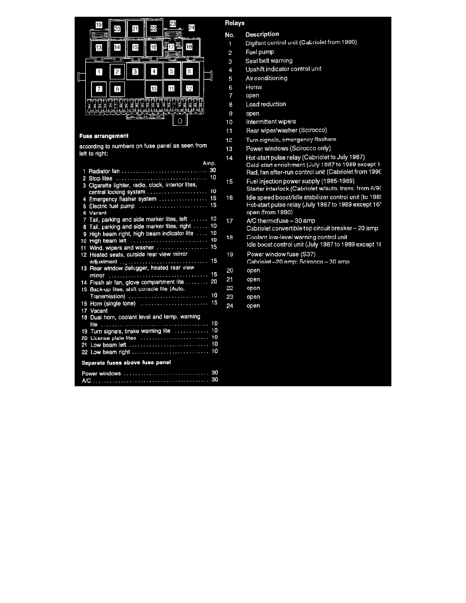
Fuse & Relay Panel
Description .................................................................................................................................................................................................. Current Track
Amplifier/radio .............................................................................................................................................................................................................. 9, 10
Antenna ......................................................................................................................................................................................................................... 9, 10
Cigarette lighter lite ............................................................................................................................................................................................................. 4
Radio connection ........................................................................................................................................................................................................... 2-10
Refrigerator 12V connector ................................................................................................................................................................................................. 1
Speaker, left front ................................................................................................................................................................................................................ 6
Speaker, left rear ................................................................................................................................................................................................................. 8
Speaker, right front .............................................................................................................................................................................................................. 7
Speaker, right rear ............................................................................................................................................................................................................... 9
Wire connectors
T2b -
double, left front footwell
T2c -
double, right front footwell
T4
-
four-point, under instrument panel, middle
T7b -
seven-point, on instrument cluster (long white housing)
T8
-
eight-point, on radio
T8a -
eight-point, on radio
