
Scirocco L4-1781cc 1.8L DOHC (1986)
Engine Control Module: Connector Views
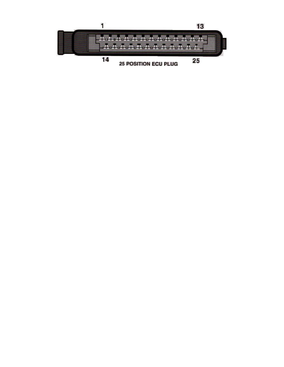
25 Position ECU Plug
Connector Layout
System
KE-Jetronic (CIS E)
Location
Plenum panel at wiper motor, engine compartment
Terminal ID
1 - Main relay power
2 - Ground
3 - ISC Valve control*
4 - ISC Valve control*
5 - Full load throttle*
6 - Diagnostic
7 - Shield ground
8 - Oxygen sensor input
9 - Ground (M/T only)
10 - Electro-hydraulic actuator control
11 - Diagnostic
12 - Electro-hydraulic actuator supply
13 - Closed throttle*
14 - Air flow sensor return
15 - Ground
16 - Diagnostic
17 - Air flow sensor Input
18 - Air flow sensor reference
19 - A/C switch*
20 - Ground*
21 - Coolant temperature sensor
22 - Ground (A/T only)
23 - N/A
24 - Starter
25 - TD signal
* Terminals applies only with engine codes:
- HT
- RD
- PL