
Vanagon F4-1915cc 1.9L (1984)
Hall Effect Sensor: Testing and Inspection
Checking Hall Generator
Requirements
Disconnect both wire plugs from idle stabilizer and connect them together
Hall control unit OK
Ignition coil OK
Wiring between Hall control unit and ignition coil OK
Connector pins and sockets on Hall-generator, distributor, and Hall control unit OK
Specified values given are valid for ambient temperatures from 0 to 40°C (32 to 104°F).
Caution: Switch multimeter to voltage range before connecting test leads
-
Disconnect center coil wire from terminal 4 of distributor and connect to ground, using jumper wire
-
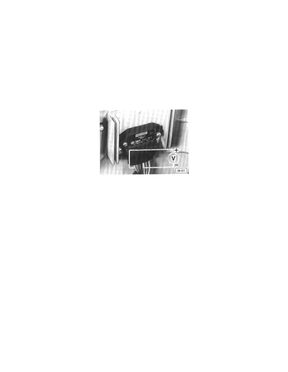
Pull rubber boot from control unit connector (with connector connected) as shown
-
Connect + (plus) wire of multimeter to terminal 6 and (minus) wire to terminal 3
-
Turn ignition ON
-
Turn engine over slowly by hand (in running direction) and watch tester reading
Voltage must fluctuate between 0 and 2 volts minimum
If NO
-
Replace Hall generator.
Note:
-
Metal shavings or other debris between the ignition control unit and heat sink can cause stress which may damage internal circuits of the
control unit:
-
When replacing ignition control unit, thoroughly clean heat sink before assembly