
240 L4-2.3L SOHC VIN 88 B230F (1986)
Engine Control Module: Description and Operation
Fuel Injection
Fuel Injection System Components
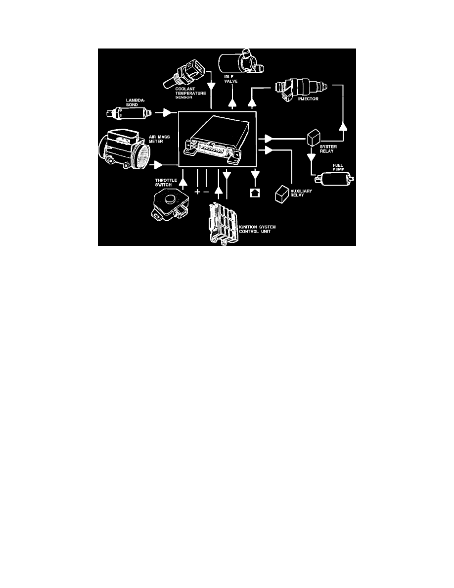
The Electronic Control Unit (ECU), located in passenger side kick panel, has a microprocessor that receives signals from various input devices
regarding engine operating conditions. This information will be evaluated in relation to pre-programmed values and it calculates the optimal injector
frequency (opening duration) to provide optimal air/fuel mixture, performance, driveability and emissions output.
Input devices (the ECU receives):
^ Ignition switch signal.
^ Oxygen sensor (lambda sond) signal.
^ Engine speed (RPM) signal from the ignition control unit.
^ Coolant temperature signal.
^ Air mass meter signal.
^ Throttle position signal.
Output devices (The ECU controls):
^ System relay ground.
^ Suppressor relay via the system relay.
^ Fuel injector ground.
^ Idle air valve.
^ Air mass meter signal to the ignition system control unit (ignition ECU input device).
^ Shift indicator light.
START-UP PROGRAM:
The cold engine start-up program provides for two injection periods per revolution. When the engine reaches operating temperature, the ECU uses
provides one injection period per revolution.
WARM-UP PROGRAM:
This program provides a richer air/fuel mixture until the engine coolant has reached a moderate temperature.
NORMAL DRIVING PROGRAM:
During normal driving, the ECU uses various input devices (mostly the air mass meter signal) to regulate injection frequency.