
240 L4-2127cc 2.1L SOHC B21F (1982)
Valve: Adjustments
1.
Remove valve cover.
2.
Rotate camshaft to position for firing No. 1 cylinder. Both cam lobes for No. 1 cylinder should point up at equally large angles. Pulley timing
mark should be at 0°.
NOTE: Always turn crankshaft (center bolt).
3.
Use a feeler gauge to check valve clearance in cylinder No. 1.
When checking, clearance should be:
Cold engine ........................................................................................................................................................... 0.010 - 0.018" (0.25 - 0.45 mm)
Hot engine ............................................................................................................................................................. 0.012 - 0.020" (0.30 - 0.50 mm)
When setting, clearance should be:
Cold engine ........................................................................................................................................................... 0.014 - 0.016" (0.35 - 0.40 mm)
Hot engine ............................................................................................................................................................. 0.016 - 0.018" (0.40 - 0.45 mm)
The same clearance is for intake and exhaust valves.
NOTE: Always check valve clearance with cylinder at top dead center. Always turn 1/4 turn after top dead center to set.
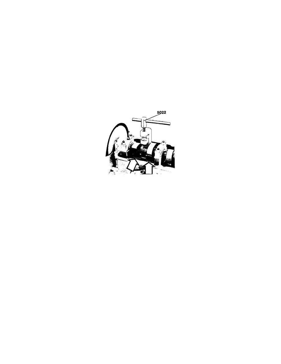
Fig. 7 Valve Adjustment
4.
If clearance is incorrect:
a.
Line up valve depressors. Turn valve depressors so that notches are at right angle to engine center line.
b.
Attach tool 5022 and depress valve depressors. Screw down tool spindle until depressor groove is just above edge and accessible with pliers.
c.
Use tool 5026 to remove disc.
d.
Use micrometer to measure disc thickness. Calculate thickness of disc to be used.
EXAMPLE: Measured clearance 0.50 mm. Correct clearance 0.40 mm. Difference +0.10 mm. Measured thickness on existing disc, 3.80
mm. Correct thickness on new disc will thus be 3.80 + 0.10 mm = 3.90 mm.
e.
Available discs are from 3.30 to 4.50 mm in increments of 0.05 mm. NOTE: Install discs with marks down.
f.
Position and oil new disc.
g.
Remove tool 5022.
5.
Proceeded to Cylinder No. 3. Rotate engine crankshaft to correct position for firing No. 3 cylinder. Check clearance as described previously. If
necessary, correct clearance.
6.
Repeat the procedure for Cylinder No. 4.
7.
Repeat the procedure for Cylinder No. 2.
8.
Turn engine a few turns and re-check all cylinders.
9.
Position valve cover gasket and install valve cover. Torque Hex 10 mm bolts to 9 ft. lbs. (12.5 Nm).