
240 L4-2127cc 2.1L SOHC B21F (1982)
Modified Blower Motor Wiring Diagram
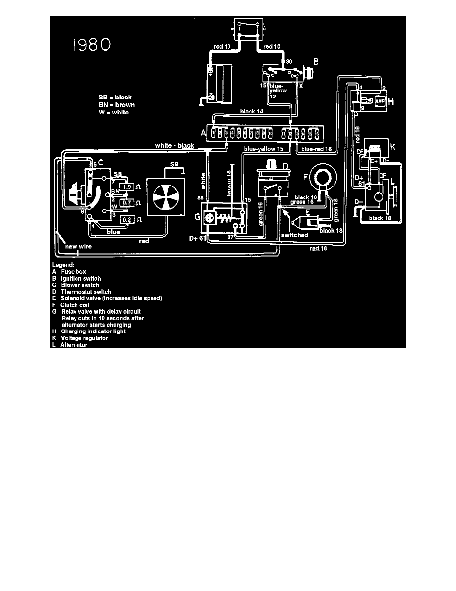
4. Install the white-black wire which was previously located in pin #3 of the old fan switch plug into pin #6 of the new switch plug. Refer to
schematic.
5. The opposite end of the white-black wire is connected to fuse #3. Refer to schematic.
6. Use a new wire and connect it to pin #5 on the fan switch plug to the switched side of the thermostat switch. Refer to schematic.
^ To determine which wire is the switched side of the thermostat, disconnect both wires and start the engine. Wait 15 seconds. Using a test light
determine which side is the hot side.
7. Connect the new wire, from pin #5 of fan switch connector, to the green thermostat switched wire. Refer to schematic.
8. Reconnect the combined new wire and switched green wire to the thermostat. Refer to schematic.
9. Take the white wire from terminal #86 on the AC-relay and connect it to the white-black wire now in pin #6 of the fan switch plug. Refer to
schematic.