
240 L4-2127cc 2.1L SOHC B21F (1982)
Coolant Temperature Sensor/Switch (For Computer): Testing and Inspection
TESTING PROCEDURE:
NOTE: Check that coolant temperature and knock sensor connectors at engine block are not interchanged.
While trouble shooting, always check the wiring, fuses and connectors for good condition and routing. Also check ground locations for good
connection. Use the wiring diagrams found in SCHEMATIC DIAGRAMS to supplement your testing efforts.
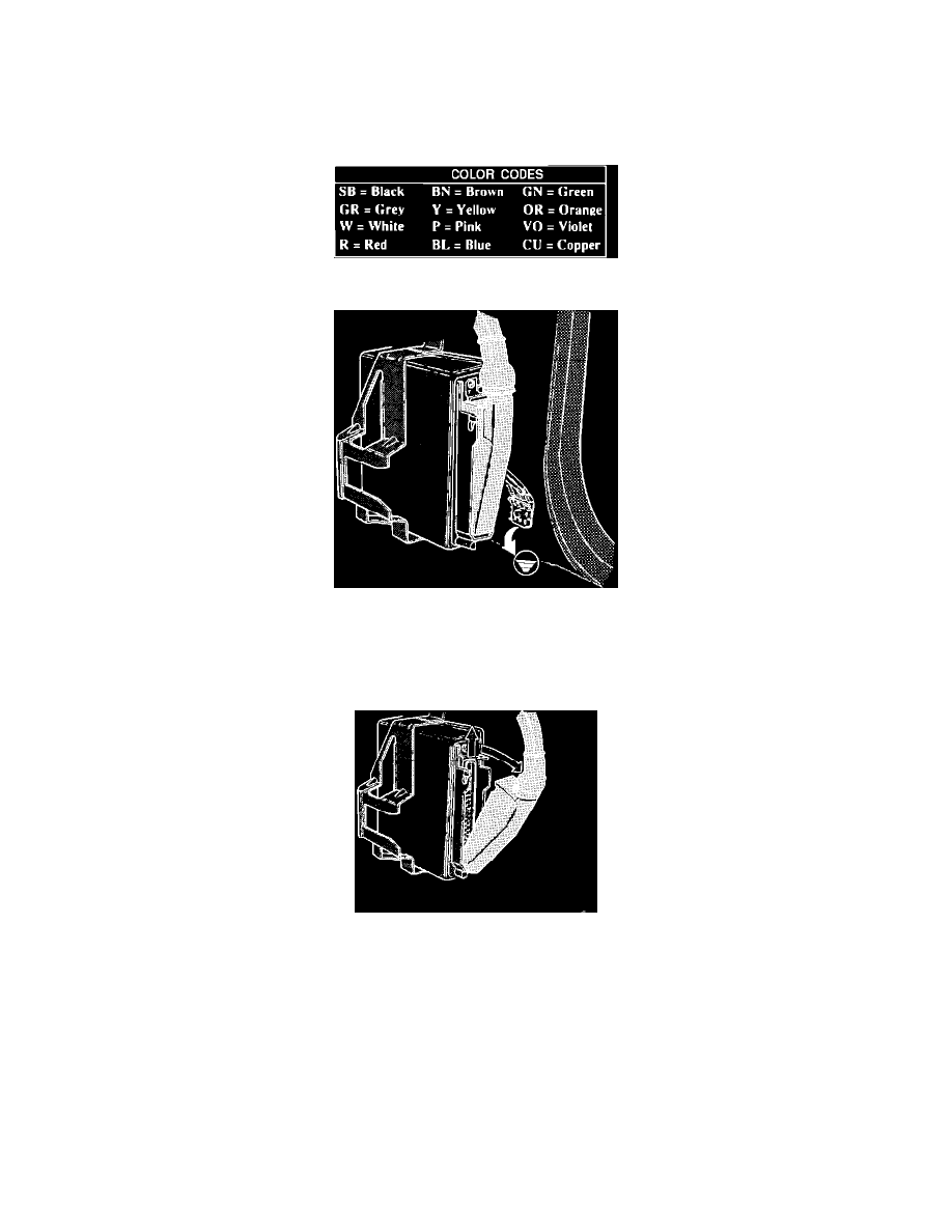
Color Code Legend
Checking ECU Ground Connections
1.
Turn ignition OFF.
2.
Access fuel injection ECU by removing the passenger side kick panel and glove compartment.
3.
Check fuel injection ECU ground connections. They should make good contact and fit tight.
Removing ECU Connector
4.
Remove the ECU connector by pressing up the latch and folding out the wire cluster.