
240 L4-2127cc 2.1L SOHC B21F (1982)
1.
After installing new bushings, seals and O-rings, install inner tube and spacer in housing. Insert rack with seal and spacer rings in inner tube. Use
tool No. 5056 as a spacer,
Fig. 5. Press in seal and spacer rings using rack and tool No. 5056. Remove tool and install lock ring.
2.
Insert outer tube in left side housing.
3.
Install lock bolt. Insert bearing sleeve in outer tube. Align hole in sleeve so it coincides with lock bolt hole in housing.
4.
Install seal and plastic ring in bearing sleeve.
5.
Insert connecting tube with rubber seal in right side housing.
6.
Install right side housing with connecting tube and seal. Align hole in housing so it coincides with lock bolt hole in the outer tube. Install lock bolt.
7.
Install outer race for pinion lower bearing. Insert pinion.
8.
Fit inner race and ball retainer on pinion using tool No. 5049. Install lock ring and nut. Do not lock the nut.
9.
Install outer race and spacer sleeve. Measure distance between spacer ring and the machined surface of the housing. Selective thickness gaskets are
available.
10.
Install the proper gasket and install tool No. 5054 in place of the cover; install valve housing and coil spring big end first.
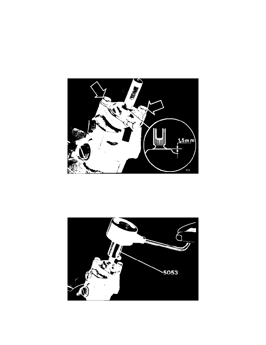
Fig. 6 Shaft shoulder to cover face clearance, with Cam Gear power steering
11.
Install valve housing cover. Shaft shoulder should be 1.5 mm (.060 in.) above cover face,
Fig. 6. Adjust position by moving lower bearing inner
race with tool No. 5049.
12.
Place pre-tensioning piston, without O-ring, in housing. Measure clearance between housing and piston faces while pressing piston against rack.
13.
Select shims to equal clearance obtained in Step 12 plus .05-.15 mm (.002-.006 in.). Install O-ring and spring for pre-tensioning piston. Install
shims and cover.
Fig. 7 Checking pinion torque. (ZF gear use tool No. 5179)
14.
Check pinion torque. Connect a torque gauge to the input shaft. Use tool No. 5053 to crank back and forth between end positions,
Fig. 7. Torque
should be .9-1.7 Nm (8-14 in. lbs.). If torque in any place is excessive, stop rack in that position and readjust-adjust the pre-tensioning device. If
rack jams with pre-tensioning device removed, rack is warped and must be replaced.