
240 L4-2127cc 2.1L SOHC Turbo B21FT FI (1982)
Air Flow Meter/Sensor: Description and Operation
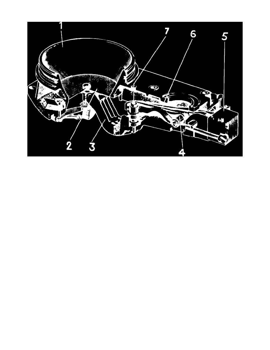
Fig. 2 Typical Bosch Air Flow Sensor
The air flow sensor, Fig. 2, continuously measures air flowing into the engine and transmits this information to the fuel distributor. The air flow sensor
consists of an air venturi (1) and an air flow sensor plate (2) which moves in the venturi. The plate is attached to a lever (3) which transmits the
movement of the plate through a flange (4) to the control plunger in the fuel distributor. The weight of the sensor plate and lever is counterbalanced by a
counterweight (5). The adjustment screw (7) is attached to a lever (6) and is used to adjust CO level.