
240 L4-2320cc 2.3L SOHC B23F FI (1983)
Modified Blower Motor Wiring Diagram
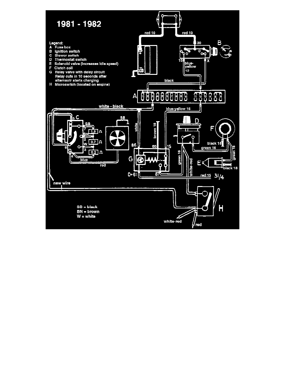
4. Install the white-black wire which was previously located in pin #3 of the old fan switch plug into pin #6 of the new switch plug. Refer to
schematic.
5. The opposite end of the white-black wire is connected to fuse #3. Refer to schematic.
6. Use a new wire and connect it to pin #5 on the fan switch plug to the microswitch terminal with the red and white-red wires attached. Refer to
schematic.
7. Take the white wire from terminal #86 on the AC-relay and connect it to the white-black wire now in pin #6 of the fan switch plug. Refer to
schematic.