
240 L4-2320cc 2.3L SOHC B23F FI (1983)
Engine Control Module: Description and Operation
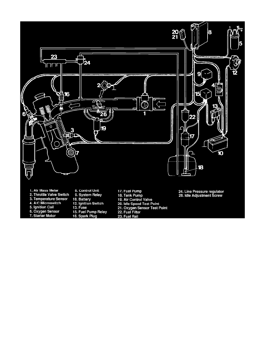
Fig. 1 LH-Jetronic II fuel injection system
The system consists of a control unit which receives information from various sensors, then uses this information to control the quantity of fuel injected
by varying the injection duration. The control unit also regulates the idle speed by varying the opening of the air control valve.