
240 L4-2320cc 2.3L SOHC VIN 82 B230F (1992)
5.
Remove connector protective sleeve.
IMPORTANT:^ Never check connections from the front. Connectors can get damaged and worsen the problem.
^ Check connections through the holes in the connector.
^ Connection pin numbers are printed on the connector side.
Checking Speedometer Signal
6.
Remove panel under instrument panel on driver side.
7.
Disconnect 12 terminal connector from speedometer.
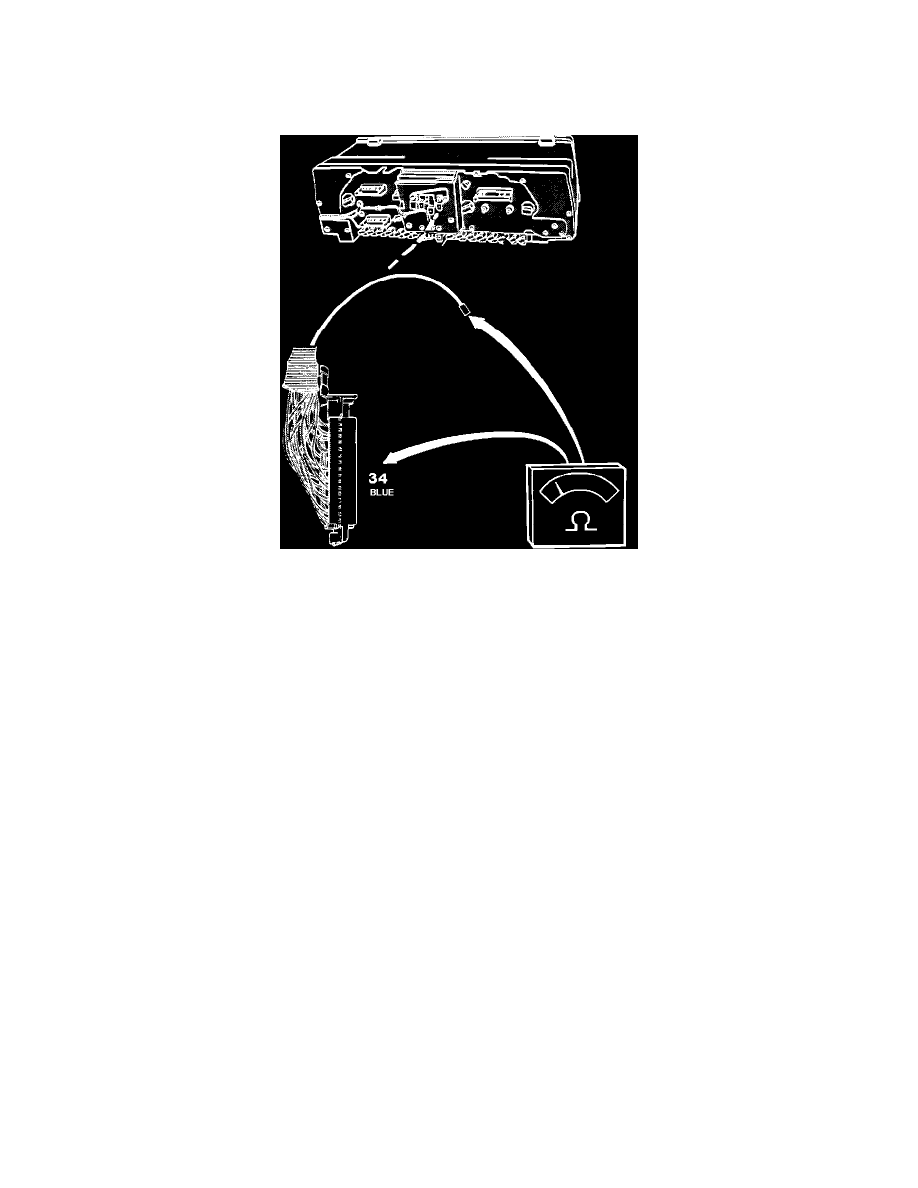
8.
Connect an ohmmeter between blue (BL) wire and pin 34 of ECU connector.
Reading: 0 ohm
9.
If reading is correct and connectors are in good condition, speedometer signal is missing. Fault is not ECU related. Use wiring diagrams (see
ELECTRICAL DIAGRAMS) to diagnose the problem.
10.
If reading is different, check wiring and connectors. Repair as needed.
11.
After testing, disconnect all test equipment, reconnect all connectors (including the ECU connector) and remount all panels.